
Introduction
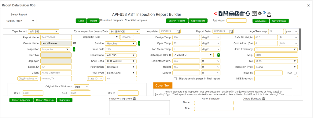
The API 653 Inspection Report Builder is a comprehensive tool designed for creating, managing, and reviewing API 653 inspection reports for Aboveground Storage Tanks (ASTs). It streamlines the inspection process by integrating data entry, calculations, and report generation into one seamless platform. This article serves as a step-by-step guide to navigating and utilizing the report builder efficiently, ensuring compliance with industry standards.
Aboveground Storage Tanks play a critical role in storing oil, chemicals, and other industrial fluids. Over time, these tanks are subject to various forms of wear, including corrosion, thinning, and structural damage, which can lead to potential safety hazards and environmental impacts. Regular inspection and evaluation, guided by API 653 standards, are essential to maintain the integrity of these tanks and extend their operational life.
The API 653 Inspection Report Builder offers a structured approach to recording inspection data, analyzing corrosion rates, calculating remaining life, and providing actionable recommendations. This tool simplifies the reporting process while ensuring accuracy and compliance with industry regulations.
Accessing the Tool
To access the API 653 Inspection Report Builder, follow these steps:
Setting Up Reports
- Navigate to the API 653 Module:
- From the main interface, choose the [API 653 Insp.] option. Then, click on the [Report Builder] button at the bottom of the page.
- Creating a New Report:
- Select [New Report +] to create a new inspection report.
- Input a unique “Report No.” in the designated field. This number serves as the unique identifier for the report.
- Selecting an Existing Report:
- To edit or continue an existing report, use the dropdown menu labeled “Select Report.” Choose the desired report from the list of previously saved inspections.
Data Entry and Customization
- Choosing the Unit System:
- In the upper-right corner of the screen, select the desired unit system: either US or Metric. This setting will apply to all numerical data entered into the report.
- Data Entry for New Reports:
- Enter all required data into the available fields, such as tank dimensions, original plate thickness, and service environment details.
- Ensure that numerical data (e.g., Design Pressure) is entered as a raw value without signifiers (e.g., 5000, not 5000 psi).
- Numerical Data Requirements
- Much of the numerical data entered on the report builder front page will be used in subform calculations. Therefore:
- Enter all numerical data without signifiers (e.g., “25” instead of “25’” or “25 ft”).
- The Original Plate Thickness in the lower-left corner will display values to the thousandths place for a professional appearance in the final report (e.g., [0.500]).
- Much of the numerical data entered on the report builder front page will be used in subform calculations. Therefore:
- Age and Previous Inspection Input
- The Age/Prev Insp. field requires a numerical value (e.g., 9, 20, 34) and not a date. This value is used to calculate corrosion rates and must correspond with the Original Plate Thickness.
- Field Customization Options:
- For dropdown menus, such as Inspector or Service, use the [ * ] button to add custom entries that are not available by default.
- These custom entries will allos the user to build the data base with data for future usage.
- Require approval from the development team to ensure accuracy and compliance with national standards (e.g., material stress values, product data values, etc.).
- For dropdown menus, such as Inspector or Service, use the [ * ] button to add custom entries that are not available by default.
- Access to Resources
- A link to the PDF Codes/Standards, File Cabinet Libraries, and Engineering Data is available in the upper-left corner for quick access to these resources.
Advanced Features and Final Steps
- Adding User Signatures
- Click on the [Signature] button at the bottom of the form to add a user signature to the report.
- Note: Changing the signature is not global. Each report requires the signature to be uploaded individually.
- Click on the [Signature] button at the bottom of the form to add a user signature to the report.
- Material Selection
- The material selection accesses a material list compliant with API-650 standards.
- Deleting Records
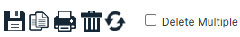
- A record may be deleted by clicking the delete icon in the upper-right corner and confirming the action.
- Printing Options
- Preview and Print:
- To preview and print the front-page section of the report (first four pages in PDF or Word format), click the Limited Print icon (printer icon with no designation) in the upper-right corner.
- Note: Always save your progress before previewing.
- To preview and print the front-page section of the report (first four pages in PDF or Word format), click the Limited Print icon (printer icon with no designation) in the upper-right corner.
- Full Report Print:
- To print the full report, click the printer icon with the “F” designation. Choose either the PDF or Word file type. The full report includes all appendices and any attached files.
- Preview and Print:
- Access to Additional Calculations
- To access extraneous AST calculations outside of the report, navigate to the Engineering Data tab and select the desired calculation.
- Cover Text Customization
- The cover text initially updates automatically based on front-page inputs.
- After the first save, users can manually edit the cover text. Avoid saving the base page until all cells are populated. Alternatively, users may delete the default text and enter custom text after saving.
- Saving Progress
- Always click the Save icon before navigating away from any page to ensure data changes are not lost.
- Spell Checking
- To perform a spell check, hover the cursor over any redlined text, right-click, and select from the suggested corrections.
- Pipe/Nozzle Practical Thickness Table
- As users scroll down the base page, the “Pipe/Nozzle Practical tmins” table will appear.
- These values default to program-generated practical thickness values but can be overwritten by users. These values will be referenced throughout the program for evaluating nozzle remaining life.
- Additional Static Data Input
- Farther down the base page, users will find empty data cells for entering additional static data.
- These entries will appear on data page 4 of the report and may be customized to suit the user’s needs.
- Progressing to Appendices
- Once all front-page data cells are populated, users can proceed to the appendices for evaluations, write-ups, recommendations, and other report-building functions.
- Always progress from left to right (Appendix A to H) when entering data in subforms, as the program cascades information progressively.
- Copy Report Feature
- To duplicate a report, click the [Copy Report] button. Enter a new name for the duplicated report.
- Note: Only front-page data and write-ups are copied. Appendices must be created separately.
- To duplicate a report, click the [Copy Report] button. Enter a new name for the duplicated report.
- Adding Company Logos
- Click the [Logo] button at the top of the form to upload the company logo for the report.
- Note: Changing the logo is not global. Each report requires the logo to be uploaded individually. To streamline this process, save logos and signatures in a dedicated folder (e.g., “AA Toolbox Support”) under My Documents for quick access.
- Click the [Logo] button at the top of the form to upload the company logo for the report.
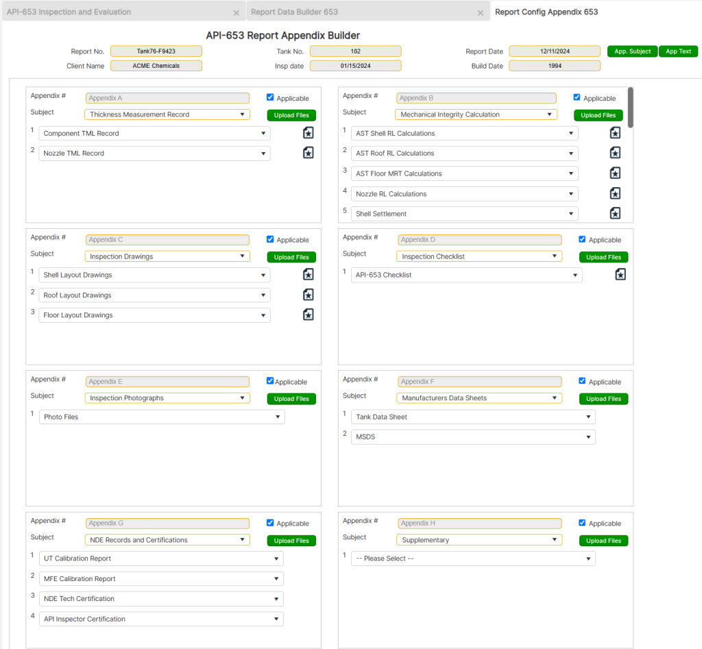
Report Configuration / Appendix
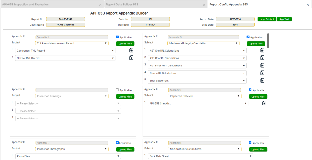
To access the Report Config. / Appendix page, start from the front page of the tool. Choose [API 653 AST], then click on the [Report Builder] button located at the bottom of the page. Select an existing report from the dropdown menu, then click on the [Report Config. / Appendix] button at the bottom left of the interface.
Appendix Overview and Functionality
The Report Appendix automatically populates with the most common appendix subjects associated with an API 653 Out-Of-Service (OOS) inspection. The section is divided into separate windows for building and editing the appendices.
- Sequential Data Entry
- Always progress from Appendix A to H when entering data into subforms. The program cascades information sequentially, ensuring accuracy as the report is completed.
- Default Text Editing
- Each appendix comes pre-filled with default text that needs to be edited to reflect the specific details of the inspection.
- Alternatively, users can delete the default text and input custom information as required.
- Pull-Down Menus
- Data cells in the appendices feature pull-down menus with user options. To add additional options, click the [App. Subject] or [App. Text] button and enter the desired details.
Customizing Appendices
Before entering data, users should review each appendix to customize its contents according to the needs of the inspection report. Specific actions include:
- Selecting and Deselecting Subjects
- Customize appendix content by selecting or deselecting relevant subjects.
- To remove a specific subject, click the pull-down arrow, select the “Please Select” option, and deselect the text.
- If an entire appendix is not applicable, uncheck the “Applicable” checkbox in the upper-right corner of that appendix.
- Adding New Subjects or Text
- To add new options to the pull-down menus:
- Click the [App. Subject] or [App. Text] button in the upper-right corner.
- Select the appendix of interest, write in the new subject or text, and click Add New Subject/Text.
- Click the Refresh icon (two circular arrows) in the upper-right corner to apply the changes.
- To add new options to the pull-down menus:
Navigation and Saving
- Save Progress Frequently
- Always click the Save icon before navigating away from any page to ensure that data and changes are not lost.
- Returning to the Base Page
- To move back to the base page from the appendix, click the Back Arrow located in the upper-right corner of the interface.
Report Component Corrosion Monitoring location (CML) Record
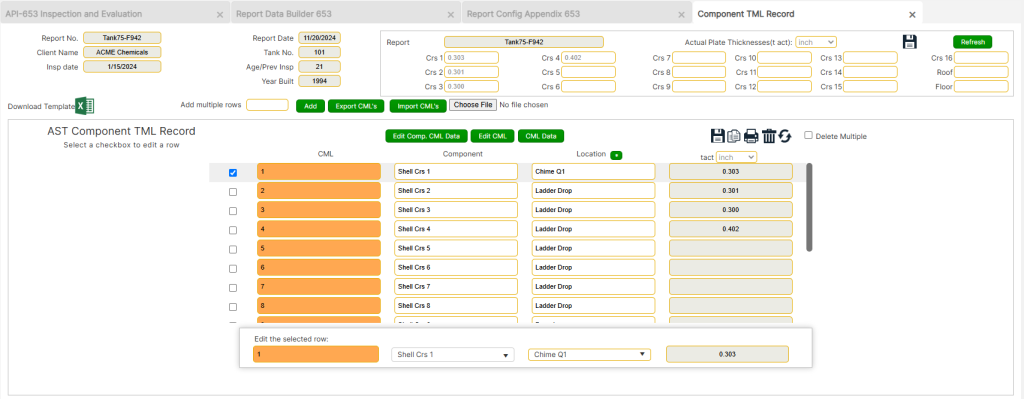
The Corrosion Monitoring Location (CML) Record section in the API 653 Inspection Report Builder allows users to document and analyze data specific to components and their corrosion rates. This feature supports efficient tracking and evaluation of key inspection data points for Aboveground Storage Tanks.
Accessing the CML Data Form
To access the CML Data Form:
- From the front page, choose [API 653 AST] and click the [Report Builder] button at the bottom of the page.
- Select an existing report from the dropdown menu, navigate to the [Report Appendix] section, and click the [Component TML Record] button under Appendix A.
- Begin entering data into the “Component TML Record” data section as prompted.
CML Data Structure
- Auto-Populating CML Data
- The CML Records will auto-populate with data as entries are added.
- “Component” entries should reflect a single description per component (e.g., all data from shell course one should have “Shell Crs 1” entered in this field).
- Location Descriptions
- The Location field should describe the specific area where thickness measurements were taken (e.g., “Chime Q1-Q2,” where “Chime” is the bottom 6 inches of the first shell course, and Q1 represents the first quadrant as defined on CAD drawings).
- Thickness Measurements
- Each CML can receive up to six thickness measurement (TML) points. The final entry is typically the lowest reading, which will be used to calculate corrosion rates and remaining life.
- The CML Descriptions appear at the top of the form to identify the CML being edited.
Entering and Managing CML Data
- New, Save, Duplicate, and Delete Records
- Add records individually or use the Duplicate function to create multiple entries. Select a CML, check the box next to it, and click the duplicate icon to create additional entries.
- Records may be deleted by clicking the delete icon in the top-right corner.
- Actual Plate Thickness Determination
- For each component, determine the Actual Plate Thickness (t act) at the top of the form. This value should represent the lowest reading across the component unless an average thickness (e.g., for hoop stress evaluation) is more appropriate.
- Editing and Correcting Data
- Use the [Edit Component Data] or [Edit CML] buttons to modify values or text. Adjustments can include deleting erroneous values or reducing decimal placements for clarity.
Importing and Exporting CML Data
- Exporting CML Data
- Click the [Export CML’s] button to export data into an Excel spreadsheet. The exported file can be used to populate additional data via copy-paste from a data log file.
- Importing CML Data
- Use the [Import CML’s] button to import data from an updated spreadsheet. Attach the file by clicking the [Choose File] button and then selecting the [Import CML’s] option.
- The imported data will overwrite any CMLs with identical numbers. Ensure the Report Number column in the spreadsheet matches the report it is being imported into.
- Transferring Data Between Reports
- Export a dataset from one report, update the report number in the spreadsheet to the desired report, and re-import the data to transfer it seamlessly.
Final Steps and Navigation
- Printing and Saving
- Save progress regularly by clicking the Save icon in the upper-right corner.
- To print the CML records, click the print icon in the upper-right corner. Always save before selecting print preview.
- Returning to Appendix Page
- To return to the Appendix page, click the Back Arrow in the upper-right corner.
Report Nozzle Corrosion Monitoring location (CML) Record
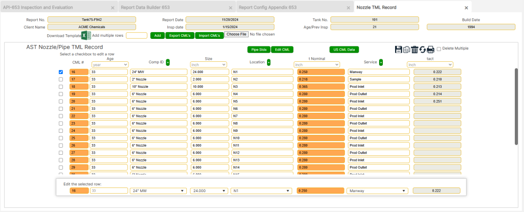
The Nozzle CML Data Form in the API 653 Inspection Report Builder enables users to document corrosion monitoring locations specific to nozzles and pipe components, ensuring accurate tracking of thickness measurements and supporting critical calculations such as corrosion rates and remaining life.
Accessing the Nozzle CML Data Form
- Navigate to [API 653 AST
]from the front page and click on the [Report Builder] button. - Select an existing report from the dropdown menu, proceed to the [Report Appendix] section, and click on the [Nozzle TML Record] button under Appendix A.
- Begin entering data in the “AST Nozzle/Pipe TML Record” data section as required.
Key Features of Nozzle CML Data
- Auto-Populated CML Numbers
- The CML numbers will auto-populate and continue from the last Component CML entry, ensuring a seamless transition between component and nozzle records.
- Data Field Requirements
- Comp ID: Enter a clear description for the nozzle (e.g., “24″ MW” or “4” Nozzle”).
- Size: Input all numerical data without unit signifiers (e.g., enter
6instead of6"or 6 in). - Location: Use identifiers (e.g., A, B, C, or MW1, N1) to locate nozzles on drawings. The default value is “A” but can be customized.
- t Nominal: Enter the nominal thickness as derived from the original nozzle specifications. Users may replace this with a previous thickness measurement for more accurate corrosion rates.
- Thickness Measurement Locations (TMLs)
- Each nozzle CML can include up to four TML points, with the final entry typically representing the lowest reading. This value is used for corrosion rate and remaining life calculations.
- Editing and Customization
- Use the [Edit CML] button to correct or replace values if needed.
- Fields with [ * ] buttons allow users to add options, such as new Component IDs or Services, to build a reusable database for future inspections.
- Pipe Specifications Reference
- The [Pipe Specs] button provides access to nominal thickness standards for nozzles, ensuring accurate data entry.
Importing and Exporting Nozzle CML Data
- Exporting CML Data
- Click the [Export CML’s] button to export data into an Excel spreadsheet. Populate the spreadsheet with additional data from a data log file using copy-paste functionality.
- Importing CML Data
- To import data, click the [Import CML’s] button, attach the spreadsheet via the [Choose File] option, and click [Import CML’s].
- The imported data will overwrite existing CMLs with matching numbers. Ensure the Report Number in the spreadsheet matches the current report.
- Data Sharing Between Reports
- Export a dataset, modify the report number in the spreadsheet to the target report, and re-import it into the program.
- Adding, Duplicating, and Deleting Records
- Add records individually or use the Duplicate function to create multiple entries based on the number of CML points or similar components.
- Records can be deleted by clicking the delete icon in the upper-right corner and confirming the action.
Best Practices for Nozzle CML Data
- Enter all numerical data precisely, using at least the ones place and to the thousandths for professional formatting (e.g., [0.500]).
- Use the lowest thickness value for remaining life calculations unless an average thickness, such as one derived for hoop stress evaluation, is appropriate.
- Regularly review imported and exported data for consistency, ensuring report numbers and CML identifiers are accurate.
Final Steps and Navigation
- Save Progress
- Always click the Save icon before navigating away from the page to ensure that all entered data and changes are preserved.
- Deleting Records
- Records can be deleted by clicking the delete icon in the upper-right corner and confirming the action.
- Printing Options
- To print the shell calculations report, click the print icon in the upper-right corner. Always save your work before selecting the print preview.
- Navigation
- After completing the Nozzle CML Data, click the Back Arrow in the upper-right corner to return to the Appendix page and proceed to the next step.
Report Shell Calculations
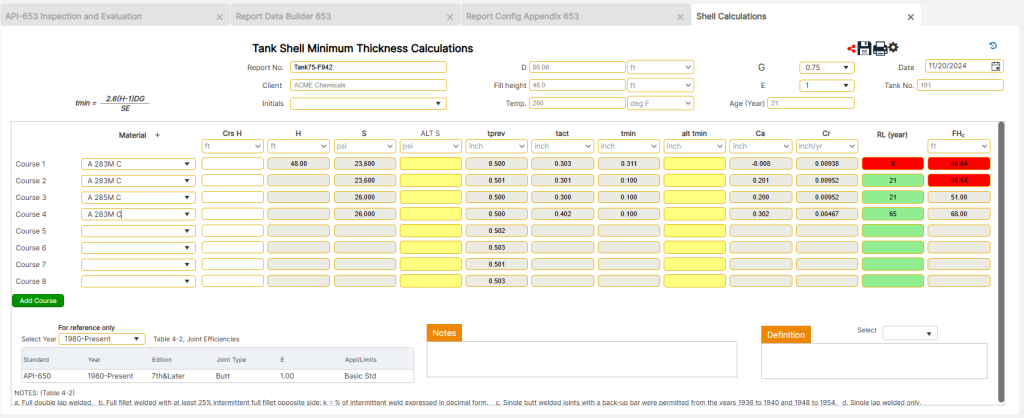
The Shell Calculations section in the API 653 Inspection Report Builder is designed to assist users in performing detailed calculations for tank shell courses, ensuring compliance with API 653 standards. These calculations consider variables such as fill height, material stress, and joint efficiency to determine the structural integrity of the tank.
Accessing the Shell Calculations
- From the front page, choose [API 653 AST] and click on the [Report Builder] button.
- Select an existing report from the dropdown menu, navigate to the [Appendix Builder] section, and click the [Shell Calculations] button under Appendix B.
- Begin performing the shell calculations by entering data in the required fields in accordance with the unit designation selected on the base page.
Shell Calculation Features
- Variable Definitions
- Definitions for calculation variables are provided in the table at the bottom-right corner.
- Use the pull-down menu and vertical scroll within the definition box to read the full text for each variable.
- Fill Height and Governing Course
- The fill height is typically the full height of the tank but may be reduced if the remaining life or tmin value is unacceptable for any course.
- When fill height adjustments are made, the governing course and fill height changes should be documented in the note section at the bottom of the page.
- Joint Efficiency
- Joint efficiency can be determined using Table 4-2, located in the lower-left corner of the form.
- Material Selection
- Materials can be selected from the API-650 material list.
- If a material is not listed, the user can enter its stress value manually by using the yellow cell under [Alt S] (next to the default stress cell).
- Clicking the [Alt S] button accesses the program’s material table (based on ASME Section 2 Part D). Select the desired material, and the form will automatically calculate its stress values for the applicable courses.
- To use a material not on the default list, add it via the Engineering Data module on the front page, ensuring it becomes available for future shell calculations.
- Alternate tmin Values
- When an alternate tmin (e.g., nominal thickness minus corrosion allowance) is required, users can enter this value in the yellow cell under Alt tmin, which will override the calculated tmin.
- Course Height (Crs H)
- Enter the measured height of the product up the course of interest (in feet) in the Crs H field. For example, if an eight-foot course contains product up to 6.5 feet, enter 6.5. Do not use tick marks (
') to denote feet; enter the number as a decimal. - The program uses this data to calculate the H value (fill height minus the sum of all Crs H values below the course of interest).
- Enter the measured height of the product up the course of interest (in feet) in the Crs H field. For example, if an eight-foot course contains product up to 6.5 feet, enter 6.5. Do not use tick marks (
- Age Variable
- The Age variable is entered as a single number (e.g.,
4, 10, 13), not a date, and is carried over from the main page entry.
- The Age variable is entered as a single number (e.g.,
- Notes Section
- Users can add notes in the lower-right corner to document observations or clarifications. These notes will appear at the bottom of the second page of the calculation report.
Final Steps and Navigation
- Save Progress
- Always click the Save icon before navigating away from the page to ensure that all entered data and changes are preserved.
- Deleting Records
- Records can be deleted by clicking the delete icon in the upper-right corner and confirming the action.
- Printing Options
- To print the shell calculations report, click the print icon in the upper-right corner. Always save your work before selecting the print preview.
- Navigation
- After completing the shell calculations, click the Back Arrow in the upper-right corner to return to the Appendix page and proceed to the next step.
Report Floor MRT Calculations
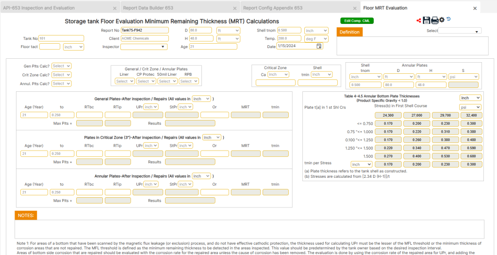
The Floor Minimum Remaining Thickness (MRT) Calculations section in the API 653 Inspection Report Builder provides tools for evaluating tank floor thickness, enabling accurate assessments for inspection and repair planning. This section includes variable definitions, threshold adjustments, and practical guidelines to ensure comprehensive calculations.
Accessing Floor MRT Calculations
To access the Floor MRT Calculations section:
- From the front page, choose [API 653 AST] and click on the [Report Builder] button.
- Select an existing report from the dropdown menu.
- Navigate to the [Appendix Builder] section and click on the [Floor MRT Calculations] button under Appendix B.
Floor MRT Calculation Features
- Variable Definitions
- Definitions for calculation variables are provided in a table located in the upper-right corner.
- Use the pull-down menu and vertical scroll within the definition box to read the full text for each variable.
- Threshold Setting for MFE Floor Exams
- Thresholds for bottom-side corrosion (RTbc) and top-side pitting (RTip) should be determined based on tank conditions and prior inspection results.
- Consult the client for historical data or previous inspection findings to set a starting basis for the threshold. Adjust variables as the inspection progresses, considering predominant findings such as:
- For clean bottoms with no relevant indications, start with a minimum of 40 mil material loss (e.g., a 0.250″ plate would set RTbc = 0.210″).
- If the bottom has few significant indications and the top has numerous indications, aim for a minimum of 40 mil material loss for RTbc.
- For numerous bottom-side indications and few top-side issues, aim for 50–70 mil material loss for RTip.
- When both sides have significant issues, balance cost-effective repairs between top and bottom pitting thresholds.
- If severe damage necessitates floor plate replacement, communicate with the client early to avoid unnecessary inspections.
- Consider coatings or CP systems as viable alternatives and how they affect results.
- Adjust the next inspection period (Or) to optimize repair scopes when feasible for the client.
- Editing CML Data
- Use the [Edit Comp. CML] button to modify CML data if a value was entered incorrectly or requires alternate adjustments.
- Notes Section
- Add any observations or clarifications in the Notes section at the bottom-right corner of the data page. These notes will appear at the bottom of the calculation report.
Final Steps and Navigation
- Save Progress
- Always click the Save icon before navigating away from the page to ensure that all entered data and changes are preserved.
- Deleting Records
- To delete a record, click the delete icon in the upper-right corner and confirm the action.
- Printing Options
- To print the floor MRT calculations report, click the print icon in the upper-right corner. Save your progress before selecting print preview.
- Navigation
- After completing the floor MRT calculations, click the Back Arrow in the upper-right corner to return to the Appendix page and proceed to the next step.
Report Nozzle Calculations
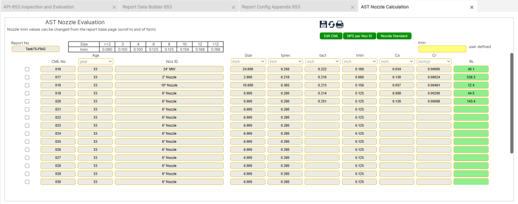
The Nozzle Remaining Life (RL) Calculations section in the API 653 Inspection Report Builder provides tools for evaluating nozzle thickness, ensuring compliance with API 570 standards. This section incorporates practical minimum thicknesses (tmin) derived from the program’s Practical tmin module, as well as options for user-defined customization.
Accessing Nozzle Calculations
To access the Nozzle RL Calculations section:
- From the front page, choose [API 653 AST] and click on the [Report Builder] button.
- Select an existing report from the dropdown menu.
- Navigate to the [Appendix Builder] section and click on the [Nozzle RL Calculations] button under Appendix B.
Nozzle Calculations Features
- Nozzle Evaluations
- Evaluations are based on previously entered data and practical tmin values recommended in API 570 for pipe thicknesses.
- The tmin values in this program are derived from the Practical tmin module (see page 75 for additional details).
- Per API 570 (Section 7.3), retirement thickness determination suggests using a greater thickness than the calculated tmin to account for:
- General and localized corrosion.
- Unanticipated loadings.
- Resistance to normal metal loss.
- Overriding Default tmin Values
- Default tmin values can be overridden using the User Defined yellow data cell at the top of the page.
- To modify, click on the CML of interest, enter the new tmin value, and repeat for all CMLs requiring updates.
- Editing CML Data
- Use the [Edit CML] button to modify or delete CML data if needed. This allows for corrections or alternate values with fewer decimal places.
- NPS per Nozzle ID Reference
- The [NPS per Noz ID] button provides quick access to pipe size details for the selected nozzle.
- Select the CML of interest, then click the [NPS per Noz ID] button in the top-left corner to view outer diameter (OD), pipe schedules, and wall thicknesses for the chosen nozzle size.
- Nozzle Standards Reference
- The [Nozzle Standards] button offers a comprehensive reference to pipe and nozzle data.
- Click on the button, then select the subject matter of interest for more information (see page 67 for details).
Final Steps and Navigation
- Save Progress
- Always click the Save icon before navigating away from the page to ensure that all entered data and changes are preserved.
- Deleting Records
- To delete a record, click the delete icon in the upper-right corner and confirm the action.
- Printing Options
- To print the nozzle calculations report, click the print icon in the upper-right corner. Save your progress before selecting print preview.
- Navigation
- After completing the nozzle calculations, click the Back Arrow in the upper-right corner to return to the Appendix page and proceed to the next step.
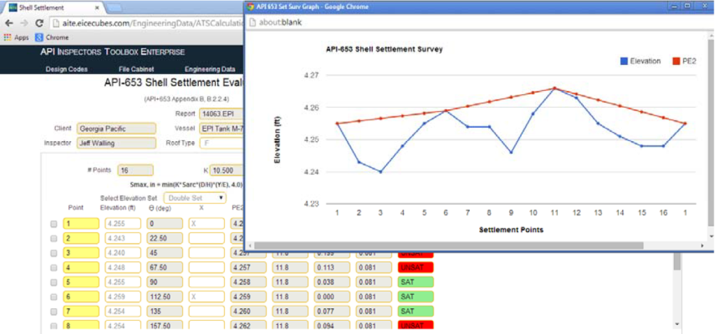
Report Shell Settlement Survey Calculations
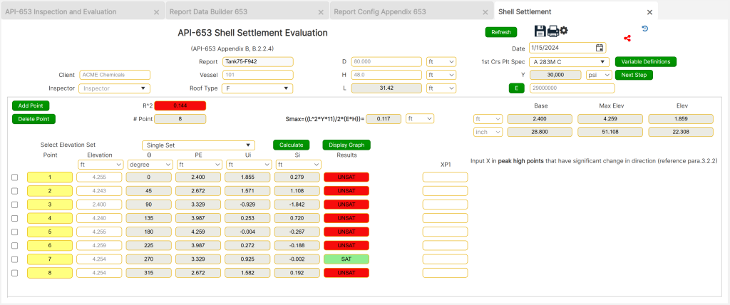
The Shell Settlement Survey Calculations section in the API 653 Inspection Report Builder enables precise evaluation of tank shell settlement based on field measurements. This feature ensures compliance with Appendix B standards and provides a detailed analysis using cosine curves and other evaluation methods.
Accessing Shell Settlement Survey Calculations
To access the Shell Settlement Survey Calculations section:
- From the front page, choose [API 653 AST] and click on the [Report Builder] button.
- Select an existing report from the dropdown menu.
- Navigate to the [Appendix Builder] section and click on the [Nozzle RL Calculations] button under Appendix B.
Shell Settlement Survey Features
- Field Measurements and Best Practices
- Measurements should begin by finding the center of the highest point of the tank and marking it as point #1 for optimal fit and accuracy.
- Always use an even number of points around the tank circumference. For example:
- For a 90-foot diameter tank, divide by 10 to get 9 points. Adjust to 10 points for better fit.
- Use 20 points for finer adjustments with 14.14 feet between each point.
- Ensure that the maximum distance between survey points does not exceed 31.42 feet.
- Data Entry and Variable Definitions
- Use the field data form to enter values into the white cells.
- Variable definitions are displayed above the input cells for convenience.
- Elevation values must be entered in feet. Convert measurements taken in inches or feet-and-inches to feet, and avoid using tick marks (
'or").
- Roof Types and Elevation Sets
- Indicate the roof type as [O] for Open Top Tank or [F] for Fixed Roof Tank.
- Select elevation sets as [Single Set] or [Double Set] depending on the number of measurement points. Double sets are recommended for more detailed evaluations.
- Cosine Curve and R² Ratio
- Click on the [Calculate] button to compute settlement based on Appendix B requirements.
- Use the [Display Graph] button to visualize a cosine curve with predicted and measured elevations.
- The best-fit cosine curve must have an R² value of at least 0.90. If the R² cell displays in red, the evaluation should follow the method described in B.2.2.5.
- Evaluation per B.2.2.5
- For R² values below 0.90, follow these steps:
- Plot the actual settlement using circumferential points.
- Identify changes in settlement slope direction to determine arc length and maximum settlement.
- Add points midway between slope changes for finer adjustments.
- Use the [Display Graph] button to plot the cosine curve and mark significant points in the XPI column. Click the [Next Step] button to proceed.
- For R² values below 0.90, follow these steps:
- Material and MOE Settings
- The program defaults to a modulus of elasticity (MOE) of 29,000,000. Adjust MOE based on material and temperature using the [E] button above the MOE cell.
- Graphing and Refinement
- High points with significant slope changes are marked in the XPI column. The final graph displays lines between the selected points for comprehensive settlement evaluation.
Figures
The figures in the Shell Settlement Survey Calculations provide critical visual aids to support evaluation and interpretation of data. Each figure corresponds to a specific step in the process, ensuring alignment with Appendix B standards.
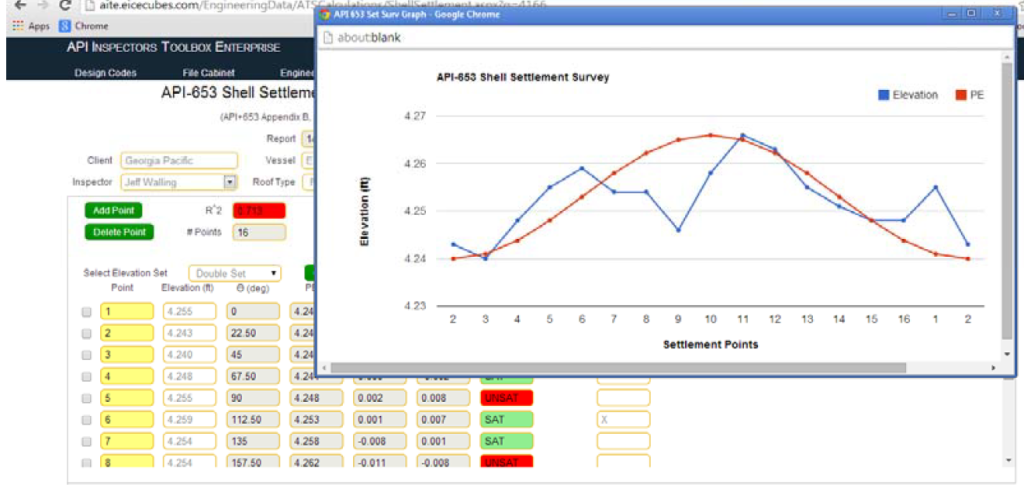
Figure 1: Shell Settlement Survey Calculation Data Entry Form
- This figure represents the data entry form used for the Shell Settlement Survey. The form includes fields for entering settlement measurements and supports evaluations as described in B.2.2.5 (refer to Appendix B, Figure B.4).
- Key actions associated with this figure include plotting actual settlement data using circumferential points as the abscissa, determining initial settlement arc length, and identifying maximum settlement.
Evaluation Methodology per B.2.2.5
- The following steps are visualized in the figures:
- The actual settlement is plotted using points around the tank circumference as the abscissa.
- An initial settlement arc length and maximum settlement are determined from the high points on the plotted data that indicate a change in direction of settlement slopes.
- Additional settlement points may be added halfway between the points indicating a change in slope direction to refine the settlement arc length, location, and magnitude of maximum settlement (this is where the [Double Set] option is used).
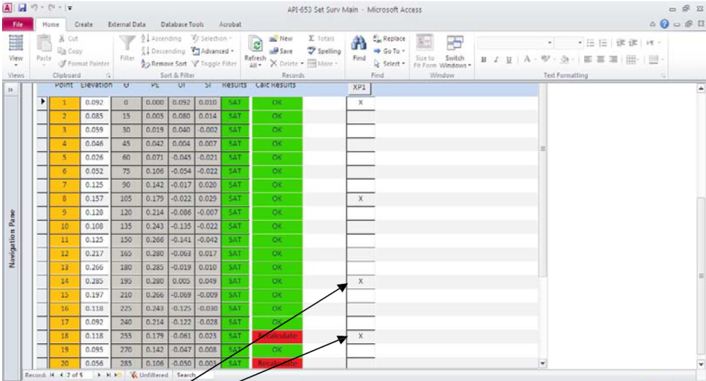
change in direction of settlement slopes under the XPI Column
Figure 2: Identifying High Points in the XPI Column
- This figure shows how to mark significant high points in the XPI column.
- Use the cosine curve graph (displayed by clicking the [Display Graph] button) to identify high points where settlement slope direction changes. Insert an “X” in the cells corresponding to these high points under the XPI column. Once all high points are marked, click the [Next Step] button to proceed.
high points selected for the significant change in direction.
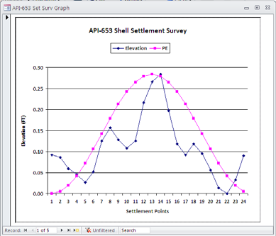
Figure 3: Final Graph of Settlement Analysis
- The final result is a graph displaying lines between the high points selected for significant changes in settlement slopes. This graph visually represents the arc length and settlement magnitude for further analysis.
Accessing Previous Records
- Use the file selection pull-down menu in the upper-left corner to access a previously saved record. This feature allows users to review prior settlement data for consistency and further evaluations.
Final Steps and Navigation
- Save Progress
- Always click the [Save] icon before navigating away to preserve data and changes.
- Deleting Records
- Records can be deleted by clicking the delete icon in the upper-right corner and confirming.
- Printing Options
- To print the settlement survey calculations, click the print icon in the upper-right corner. Save progress before selecting print preview.
- When using B.2.2.5 evaluation, print the first page showing the cosine graph and R² value, followed by the next-step report.
- Navigation
- After completing the settlement survey calculations, click the [Back Arrow] in the upper-right corner to return to the Appendix page and proceed to the next step.
Report AST Checklists
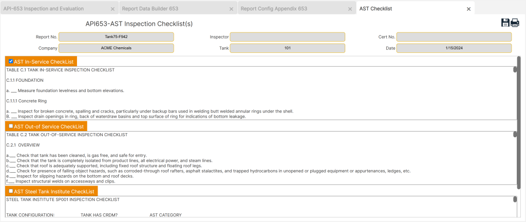
The AST Checklists section in the API 653 Inspection Report Builder facilitates the documentation of inspection items for Aboveground Storage Tanks (ASTs). This feature allows users to create and include checklists in the final inspection report, ensuring thorough and standardized evaluation.
Accessing AST Checklists
To access the AST Checklists section:
- From the front page, choose [API 653 AST] and click on the [Report Builder] button.
- Select an existing report from the dropdown menu.
- Navigate to the [Appendix Builder] section and click on the [Report Checklist] button under Appendix D.
AST Checklist Features
- Report Checklist Structure
- The checklist section is divided into three separate windows, enabling users to organize and build the report checklist systematically.
- Use the [Select Checklist] button at the top-left corner of the checklist to choose the items that should be included in the report.
- Marking Inspection Items
- Scroll through the checklist and place an “X” in the center of the line for relevant items that were checked during the inspection.
- To enter an “X,” position the cursor in the center of the check line, backspace, and type an uppercase “X” ([Caps] key enabled).
- Checklist Management
- Records can be deleted by clicking the delete icon in the upper-right corner and confirming the action.
- Ensure all entries are accurate and complete before proceeding to other sections.
Final Steps and Navigation
- Save Progress
- Always click the [Save] icon before navigating away from the page to ensure all data and changes are preserved.
- Printing Options
- To print the checklist, click the print icon in the upper-right corner. Save your progress before selecting print preview.
- Navigation
- After completing the checklist, click the [Back Arrow] in the upper-right corner to return to the Appendix page and proceed to the next step.
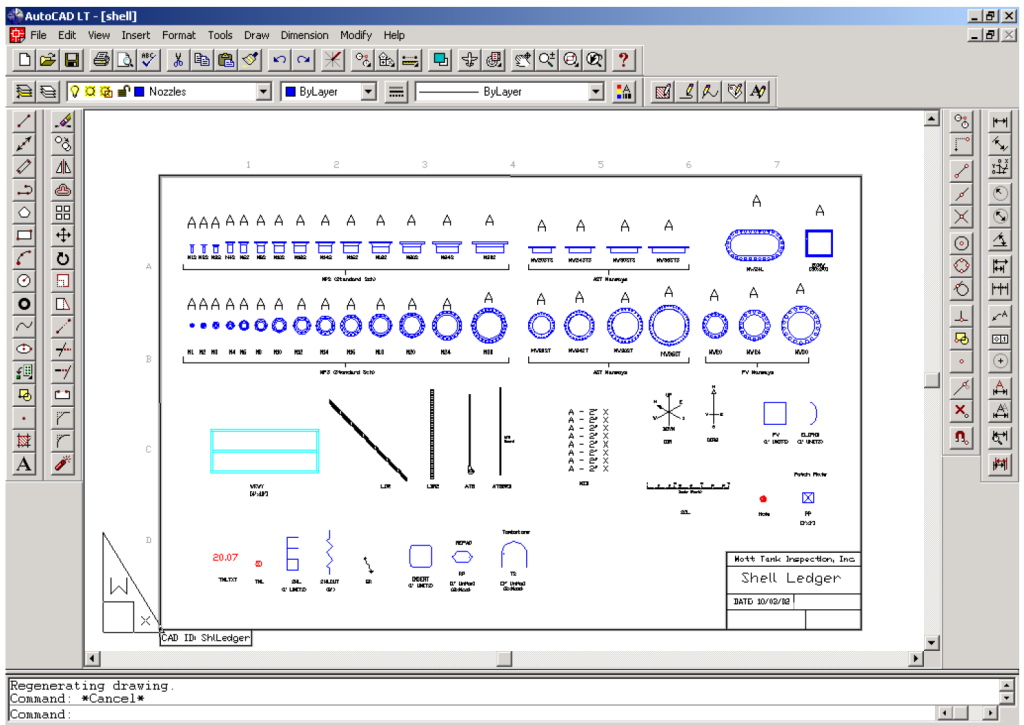
Report Shell AutoCAD Inspection Drawings
The Shell AutoCAD Inspection Drawings section in the API 653 Inspection Report Builder enables users to create or upload inspection drawings for detailed tank shell analysis. Users have the option to upload PDF drawings or utilize a pre-designed AutoCAD template. This function requires AutoCAD (1997 or later version) and field data relevant to the project.
Accessing AutoCAD Inspection Drawings
To access the AutoCAD Inspection Drawings section:
- From the front page, choose [API 653 AST] and click on the [Report Builder] button.
- Select an existing report from the dropdown menu.
- Navigate to the [Appendix Builder] section and click on the icon (page with a star) under Appendix C.
- Save the file to a project folder and print out the ledger drawing for reference while building the shell drawing.
AutoCAD Inspection Drawing Process
Once the CAD drawing is open and saved to a project folder, complete the following steps using the field data sheets and drawings:
Edit Title Blocks and Drawing Text
- Switch to paper space (type PS on the command line) and edit all title blocks and drawing text related to the specific report information.
- Update the company name, date, and any other required text to conform to your company’s drawing protocols.
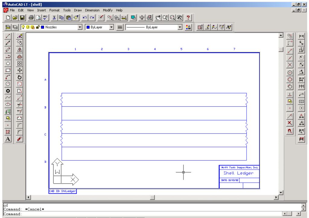
Insert and Scale the Shell Block
- Switch to model space (type MS on the command line) and enter the following commands:
- Command:
Insert -> SHL - Insertion Point:
0,0 - X Scale Factor: Enter the tank circumference in feet without any unit signifiers (e.g., for a 35-foot diameter tank, calculate 35×π=11035 \times \pi = 11035×π=110, and enter “110”).
- Y Scale Factor: Enter the tank shell course height in feet without any unit signifiers (e.g., for an 8-foot height, enter “8”).
- Rotation Angle: Enter default.
- Command:
- Command: Zoom -> Limits. If this does not bring the shell into full view, zoom manually to a scale that provides a full view.
- Command: Explode to break apart the SHL block.
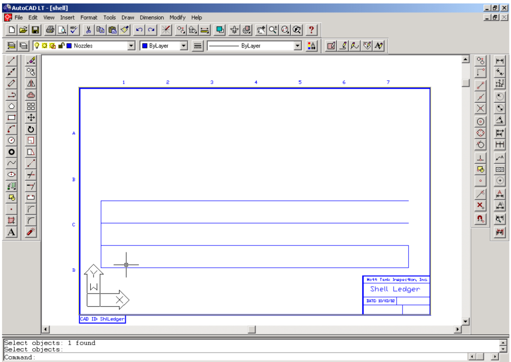
Customize the Shell Drawing
- Copy and paste the existing three-tier shell drawing to create the required number of shell courses.
- Delete the vertical weld seams above weld seam #1 at point 0,0 in the upper courses that do not align with the first course. Replace them by drawing vertical weld seams that align with field data.
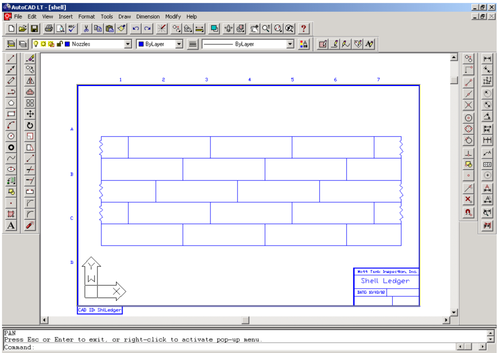
Insert Shell Cut Patterns
- Enter the following commands for shell cut patterns:
- Command: Insert -> SHLCUT
- Insertion Point: Snap to the top of vertical weld seam #1.
- X Scale Factor: Enter default.
- Y Scale Factor: Enter default.
- Rotation Angle: Enter default.
- Copy and paste the SHLCUT to all remaining vertical placements above weld seam #1. Mirror these placements to the weld seam on the opposite side.
Offset Weld Seams
- Offset weld seam #1 in accordance with the field data sheet. For example, for a 30-foot offset:
- Command: Offset -> 30. Click on weld seam #1 and left-click to offset to the right of the seam.
- Repeat until all weld seams are drawn on the first course. Copy these weld seams to any other courses that align with the first course.
Insert Nozzles
- Reference the shell ledger drawing for nozzle nomenclature. For example:
- Command: Insert -> MW24 (for a 24-inch manway).
- Insertion Point: Enter coordinates (e.g., X = 4, Y = 30).
- X Scale Factor: Enter default.
- Y Scale Factor: Enter default.
- Rotation Angle: Enter default.
- Explode the nozzle block and edit the text to associate it with CML points.
- Repeat for all nozzles according to the field data.
Insert Ladders
- Insert ladders as indicated on the field drawings:
- Command: Insert -> LDR.
- Insertion Point: Enter coordinates (e.g., X = 25, Y = 12).
- X Scale Factor: Enter default.
- Y Scale Factor: Enter default.
- Rotation Angle: Enter default.
- If the ladder runs in the opposite direction of the default, use the Mirror command to flip it to the correct orientation before exploding.
- Explode the LDR block and edit it to conform to the field drawing.
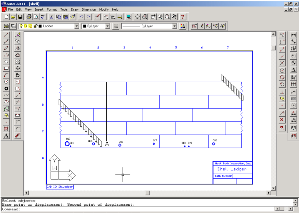
Add Additional Entities
- Insert any other required entities, such as ATG, GR, or handrails, as indicated on the field drawings. For example:
- Command:
Insert -> ATG. - Insertion Point: Enter coordinates (e.g., X = 27, Y = 4).
- X Scale Factor: Enter default.
- Y Scale Factor: Enter default.
- Rotation Angle: Enter default.
- Command:
- Explode the ATG block and edit it to conform to the field drawing.
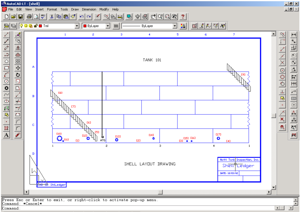
Add Weld Seam Numbers and CML Points
- Label all weld seams and add CML points according to field data.
For Large Tanks
- For large tanks, draw the shell as one complete drawing and then save separate drawings for individual sections as needed. Typically, limit each drawing to two to four shell courses to ensure that all entities are recognizable and text is legible.
- Edit the title block to reflect the numbering sequence of the drawings.
Final Steps and Navigation
- Save Progress
- Always click the [Save] icon before navigating away from the page to ensure all data and changes are preserved.
- Printing Options
- To print, click the print icon in the upper-right corner. Save your progress before selecting print preview.
- Navigation
- After completing the drawings, click the [Back Arrow] in the upper-right corner to return to the Appendix page and proceed to the next step.
Report Roof/Floor AutoCAD Inspection Drawings
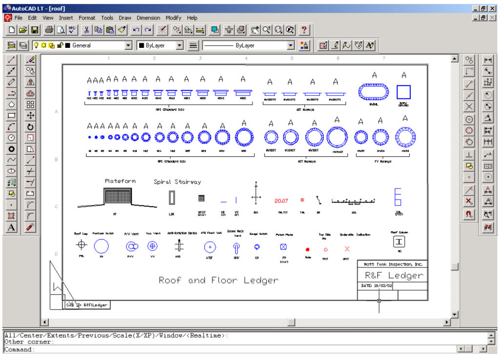
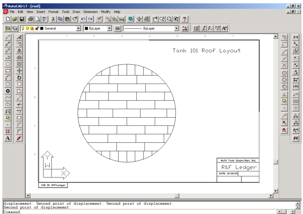
The Roof/Floor AutoCAD Inspection Drawings section in the API 653 Inspection Report Builder allows users to create detailed layouts for tank roofs and floors using AutoCAD. This process incorporates field data and drawings to ensure accurate representations for inspection purposes. The principles apply to both roof and floor layouts, with specific appurtenances like nozzles, platforms, stairways, roof columns, and sumps differing between the two.
Accessing Roof/Floor AutoCAD Inspection Drawings
To access the Roof/Floor AutoCAD Inspection Drawings:
- From the front page, choose [API 653 AST] and click on the [Report Builder] button.
- Choose [New Report] or [Select Existing Report] from the popup screen.
- Click on the [CAD Drawings] button at the bottom-right corner, then click on the [Dwgs/roof.dwg] link to open the AutoCAD template.
- Save the file to a project folder and print out the ledger drawing for reference when building the layout.
AutoCAD Inspection Drawing Process
Once the CAD drawing is open and saved as a Roof or Floor Layout Drawing, complete the following steps referencing field data sheets and drawings. The steps below describe roof layout processes but also apply to floor layouts with differences in appurtenances.
Edit Title Blocks and Drawing Text
- Switch to paper space (type PS on the command line) to edit all title blocks and drawing text related to the specific report.
- Update company name, date, and other necessary information to conform to the user company’s drawing protocols.
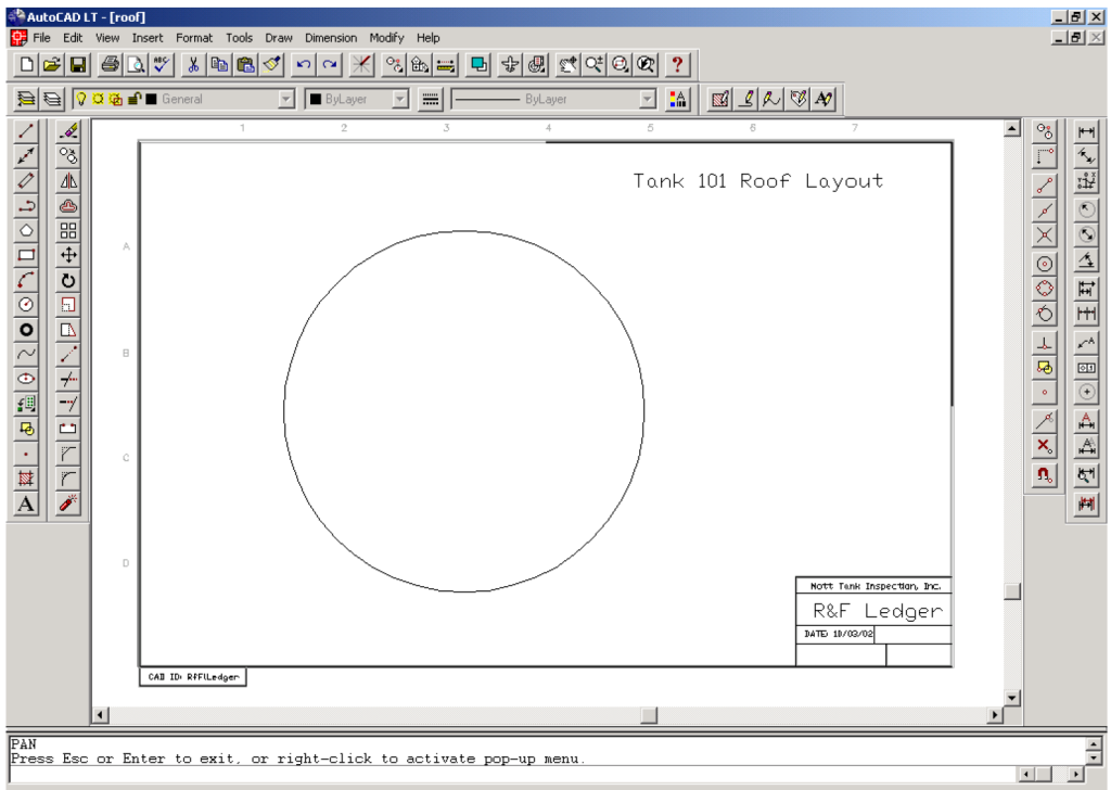
Create the Roof Circle in Model Space
- Switch to model space (type MS on the command line) and enter the following:
- Command:
C(Circle). - Center Point:
0,0. - Diameter: Enter the tank diameter (e.g., for a 70-foot diameter tank, type
70).
- Command:
- Command:
Zoom Allto bring the roof circle into full view, leaving room around the perimeter for inserting platforms and stairways.
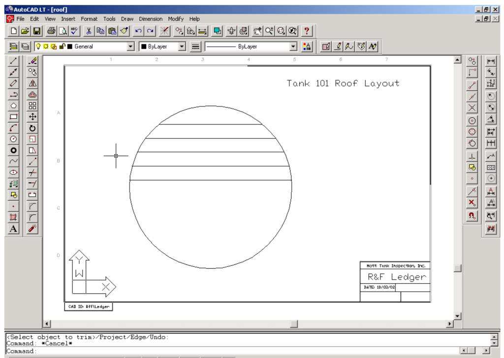
Draw Horizontal Weld Seams
- Use field drawings to determine horizontal weld seam offsets (nominally 6 feet apart) from the roof center. Then:
- Command:
L(Line) -> Snap to the left and right quads. - Command:
Offset -> 3(for the initial line). - Select the weld line -> Click above the line and delete the original centerline.
- Command:
Offset -> 6for subsequent lines. - Repeat until all upper weld lines are in place per field drawings. Trim any lines extending outside the roof perimeter.
- Command:
Add Vertical Weld Seams
- Determine the placement of vertical weld seams for the upper half of the drawing. Draw these lines freely, keeping close to the actual as-built layout.
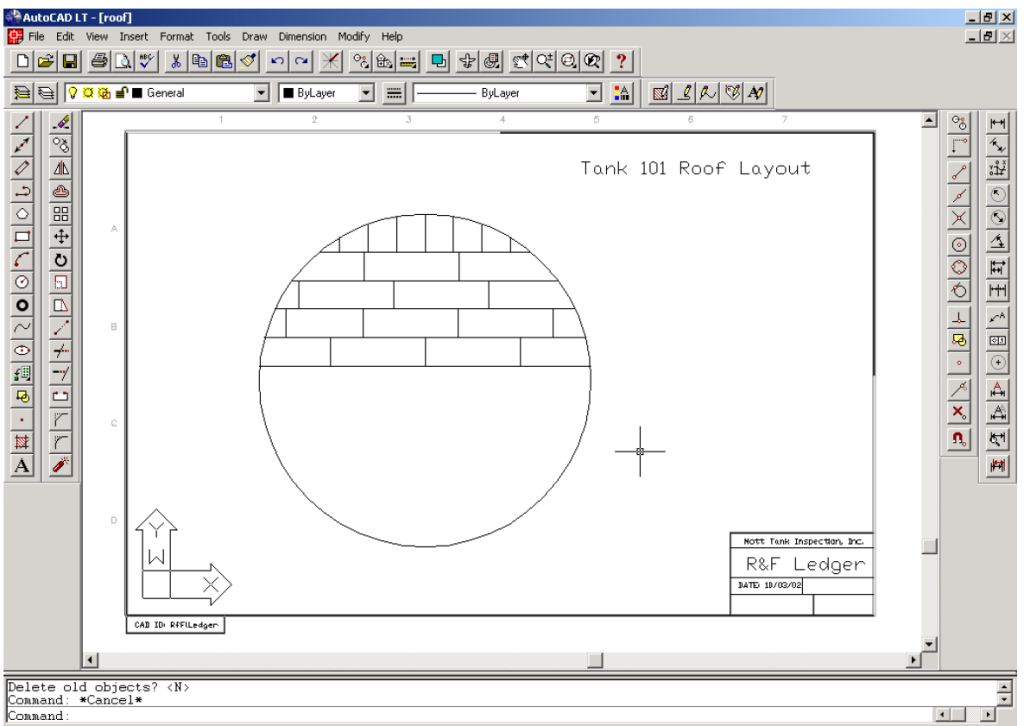
Mirror Command
- For the lower half, mirror the upper half to create an inverted layout. Use the Mirror command and ensure “delete old objects” is selected. Edit any differences and draw vertical weld seams connecting the upper and lower halves as needed.
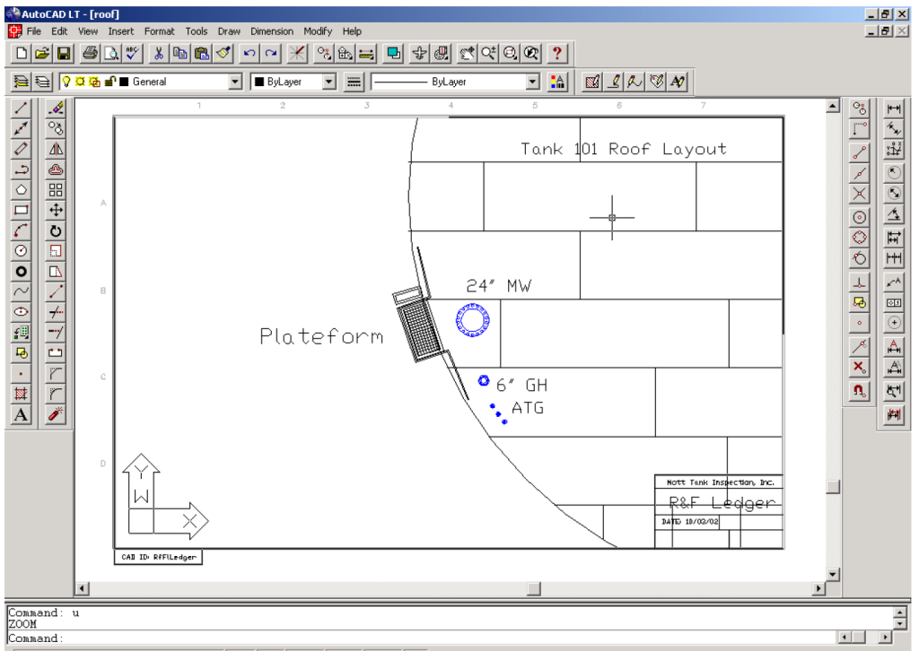
Insert Nozzles
- Reference the Roof Ledger drawing for nozzle nomenclature. For example:
- Command:
Insert -> MW24(for a 24-inch manway). - Insertion Point: Select the location from the field drawings.
- X Scale Factor: Enter default.
- Y Scale Factor: Enter default.
- Rotation Angle: Enter default.
- Command:
- Explode the nozzle block and edit text to match associated CML points.
- Repeat for all nozzles per field data.
Insert Top Platform and Ladder
- Add platforms:
- Command:
Insert -> PF. - Insertion Point: Top quad.
- X and Y Scale Factors: Enter default.
- Rotation Angle: Enter default.
- Command:
- Use the Rotate command to adjust the platform’s position per field drawings, ensuring proper handrail orientation. Explode the platform block and scale text for legibility if needed.
- Add ladders:
- Command:
Insert -> LDR. - Insertion Point: Near the platform, as indicated in field drawings.
- X and Y Scale Factors: Enter default.
- Rotation Angle: Enter default.
- Command:
- Explode the ladder block, move the text to a legible location, and use the Rotate command to align the ladder with the platform.
Ladder Array
- Determine the number of steps required using the rule of thumb:
- Number of steps = Tank height in feet (e.g., a 48-foot height requires 48 steps).
- Determine degree to array: 360×(Height/Circ)=X or 360×(48/220)=78 (if CCW or -78 if CW).
- Use array command: select ladder rung (include both entities).
- R/P: Enter P (polar).
- Base/Center: type “Center” and pick the circle (roof perimeter).
- Number of items: enter the number determined above (i.e., 48).
- Angle to fill (+ = CCW, – = CW) (degree): enter the number determined in k above in (+) or (-) array (i.e., -78 for Clockwise in this example).
- Rotate Object (Y): enter default.
- Zoom to previous view and adjust Zoom at this point to fill most of the drawing field.
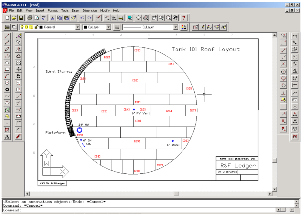
Add Additional Entities and CML Points
- Insert or draw other required entities, such as ATG, GR, or handrails, as indicated in the field drawings.
- Add CML points to align with inspection data.
Final Steps and Navigation
- Save Progress
- Always click the [Save] icon before navigating away from the page to ensure all data and changes are preserved.
- Printing Options
- To print, click the print icon in the upper-right corner. Save your progress before selecting print preview.
- Navigation
- After completing the drawings, click the [Back Arrow] in the upper-right corner to return to the Appendix page and proceed to the next step.
Report Inspection Photograph
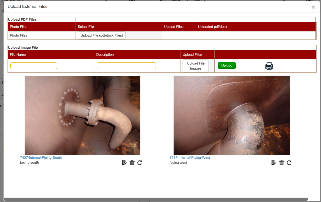
The Inspection Photographs section in the API 653 Inspection Report Builder allows users to develop and upload inspection photographs into a Word document. A link to the File Cabinet is provided to access a pre-designed Word document to aid in this process.
Accessing Inspection Photographs
To access the Inspection Photographs section:
- From the front page, choose [API 653 AST] and click on the [Report Builder] button.
- Select an existing report from the dropdown menu.
- Navigate to the [Appendix Builder] section and click on the [Upload Files] button under Appendix E.
Inspection Photograph Features
Once the Inspection Photographs Appendix is open, complete the following steps:
- Enter caption text in the header space for the photo to be uploaded.
- Click the [Choose File] button and locate the photo you wish to upload.
- Click the [Upload] button to add the photo to the document.
- Repeat steps 1–3 until all photographs have been uploaded.
Final Steps and Navigation
- Save Progress
- Always click the [Save] icon before navigating away from the page to ensure all data and changes are preserved.
- Navigation
- After completing the photograph uploads, click the [Back Arrow] in the upper-right corner to return to the Appendix page and proceed to the next step.
All other Appendices
The remaining appendices in the API 653 Inspection Report Builder allow users to upload additional files, such as PDF attachments, for inclusion in the report. These files provide supplementary data, calculations, or documentation relevant to the inspection.
Accessing Other Appendices
To access the remaining appendices:
- From the front page, choose [API 653 AST] and click on the [Report Builder] button.
- Select an existing report from the dropdown menu.
- Navigate to the [Appendix Builder] section and click on the [Upload Files] button under the appendix of interest.
Appendix Upload Process
Once the Inspection Appendix page is open, complete the following steps:
- Click the [Choose File] button and locate the PDF file you wish to upload.
- Click the [Upload] button to attach the file to the appendix.
- Repeat steps 1–2 until all necessary files are uploaded.
Final Steps and Navigation
- Save Progress
- Always click the [Save] icon before navigating away from the page to ensure all data and changes are preserved.
- Navigation
- After completing file uploads, click the [Back Arrow] in the upper-right corner to return to the Appendix page and proceed to the next step.
Report Write-up and Recommendations
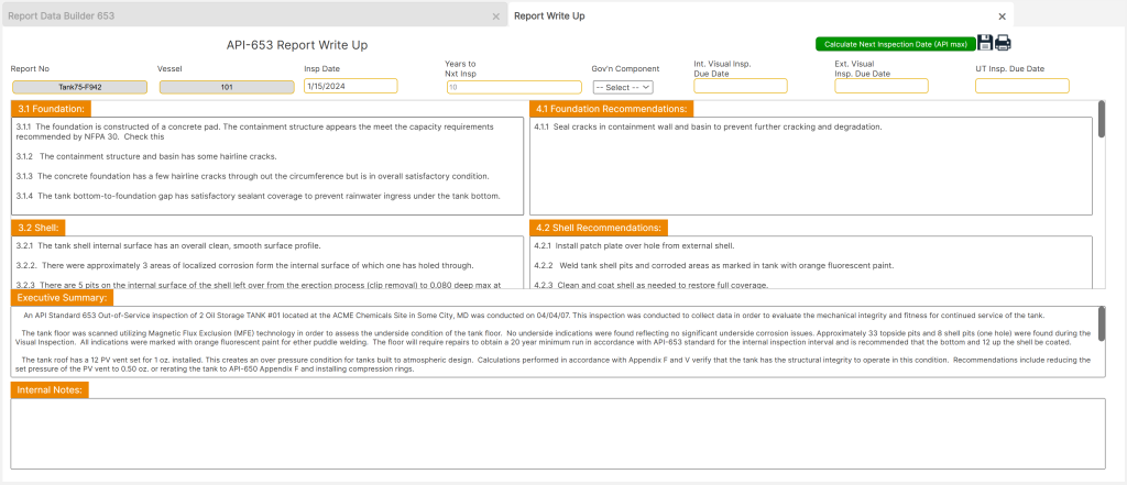
To access the Write-up and Recommendations page, start from the front page of the tool. Navigate to [API 653 AST], click on the [Report Builder] button at the bottom of the page, and select the desired report from the dropdown menu. Finally, click on the [Report Write-up] button to proceed.
This section provides detailed functionality for documenting findings and recommendations for the inspected components. It includes tools and windows to ensure thorough and accurate reporting.
Key Features
- Quick Access to Codes
- The [Codes] button offers fast navigation to referencing codes, enabling users to align their recommendations with API standards.
- Next Inspection Date Calculation
- The [Calculate Next Inspection Dates (API max)] button calculates inspection intervals based on the maximum allowed by code. This interval may be adjusted if corrosion rates suggest a shorter timeline.
- Default Write-up Text
- The page includes default write-up and recommendation text. Users can edit this text to reflect specific findings or delete it entirely to input custom recommendations.
- To correct spelling errors, place the cursor over red-highlighted text, right-click, and select from suggested corrections.
- Inspection Interval and Governing Component
- Cells across the top of the page allow for determining next inspection dates and identifying the governing component (typically the component with the least remaining life).
- The “Years to Next Insp.” field requires a numerical value without signifiers (e.g.,
2,4,5), typically defaulting to 5 years.
- UT Results Summary and Recommendations
- This section should address all calculation results and highlight any issues identified during component evaluations.
Executive Summary (ES)
- Editing Default Text
- The Executive Summary (ES) text includes default content, which should be reviewed and edited to reflect associated information. Users may delete the default text and enter new details as needed.
- Common discrepancies addressed in the Executive Summary include:
- Items with significant cost implications.
- Issues that limit tank operating parameters.
- Copying from the Body of the Report
- Items detailed in the body of the report can be summarized in the ES with minor edits for clarity.
- Display Location
- The Executive Summary does not appear in the Report Write-up preview but is visible on the main page preview.
Final Steps and Navigation
- Save Progress
- Always click the Save icon before navigating away from the page to prevent data loss.
- Deleting Records
- Records may be deleted by clicking the Delete icon in the upper-right corner and confirming the action.
- Printing Options
- To print, click the Printer icon in the upper-right corner. Save the report before printing to ensure all changes are included.