
Live Load: Cooper E-80 Railroad Load on Buried PE Pipe
This calculation based on normal RR loading and analyzed for depths of cover from 6 to 14 feet. The calculation only accounts for up to 80,000 lb/ft railway load, with impact factor.
Dead/Earth Load
A. Prism Load
𝑃𝑝 = 𝑤𝐻
𝑃𝑝 = Vertical Soil Pressure,[lb/ft2]
𝑤 = Unit Weight of Soil,[lb/ft2]
𝐻 = Height of Soil Above Pipe Crown,[ft]
B. Marston Load (ASCE Manual No.60)
𝑃𝑚 = 𝐶𝑑𝑤𝐵𝑑
𝑃𝑚 = Vertical Soil Pressure,[lb/ft2]
𝑤 = Unit Weight of Soil,[lb/ft2]
𝐵𝑑 = Trench Width at Pipe Crown,[ft]
𝐶𝑑 = Load/Trench Coefficient
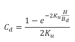
𝑒 = Base of Natural Logarithm,[2.71828]
𝐾 = Rankine Earth Pressure Coefficient
𝐾 = 𝑡𝑎𝑛2 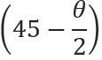
𝜃 = Angle of Internal Soil Friction, [°]
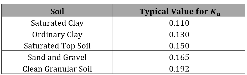
𝑢 = Coefficient of Friction between Backfill and Trench Sides
C. Combined Prism and Marston Load
For flexible pipe, a more conservative method is to use a soil pressure load in between prism and Marston load:
𝑃𝑐 = 0.6𝑃𝑚 + 0.4𝑃𝑝
𝑃𝑐 = Combined Load or Modified Arching Soil Pressure, [lb/ft2]
Live Load: Cooper E-80 Railroad Load on Buried PE Pipe
𝑃𝐿 = 𝐹𝐸80(𝐻)
𝑃𝐿 = Vertical Soil Pressure due to Surcharge Load [lb/ft2]
𝐹𝐸80 = Live Load Transfer to Pipe [lb/ft2] (see table)
𝐻 = Soil Height above Pipe Crown [ft]
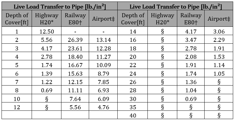
* Simulates a 20-ton truck traffic load, with impact factor
† Simulates an 80,000 lb./ft railway load, with impact factor
‡ Applies to 180,000 lb. dual-tandem gear assembly, with 26 in. spacing between tires and 66 in. center to center spacing between fore and aft tire under a rigid 12 in. pavement, with impact factor
§ Negligible influence of live load on buried pipe
Pipe Deflection is calculated using Spangler’s Modified Iowa Formula:
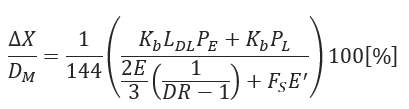
∆𝑋 = Horizontal Deflection[in]
𝐷𝑀 = Mean Diameter[in]
𝐾𝑏 = Bedding Factor
𝐿𝐷𝐿 = Deflection Lag Factor
𝑃𝐸 = Vertical Soil Pressure due to Earth Load[lb/ft2]
𝑃𝐿 = Vertical Soil Pressure due to Live Load]lb/ft2]
𝐸 = Apparent Modulus of Elasticity of Pipe Material[psi]
𝐸′ = Modulus of Soil Reaction[psi]
𝐹𝑆 = Soil Support Factor
𝐷𝑅 = Standard Dimension Ratio DR 
𝐷𝑜 = Pipe Outside Diameter [in]
𝑡 = Minimum Pipe Wall Thickness [in]
- Modulus of Soil Reaction (E’) – Average Values for Iowa Formula (see table in section 2.0)
- Modulus of Soil Reaction (E’) – Values of E’ for Pipe Embedment (see table in section 2.0)
- Values of E’n Native Soil Modules of Soil Reaction (see table in section 2.0)
- Soil Support Factor (see table in section 2.0)
Pipe Wall Compressive Stress
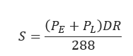
𝑆 = Pipe Wall Compressive Strength [psi]
𝑃𝐸 = Vertical Soil Pressure due to Earth Load[lb/ft2]
𝑃L = Vertical Soil Pressure due to Live Load [lb/ft2]
𝐷𝑅 = Standard Dimension Ratio DR 
𝐷𝑜 = Pipe Outside Diameter [in]
𝑡 = Minimum Pipe Wall Thickness [in]
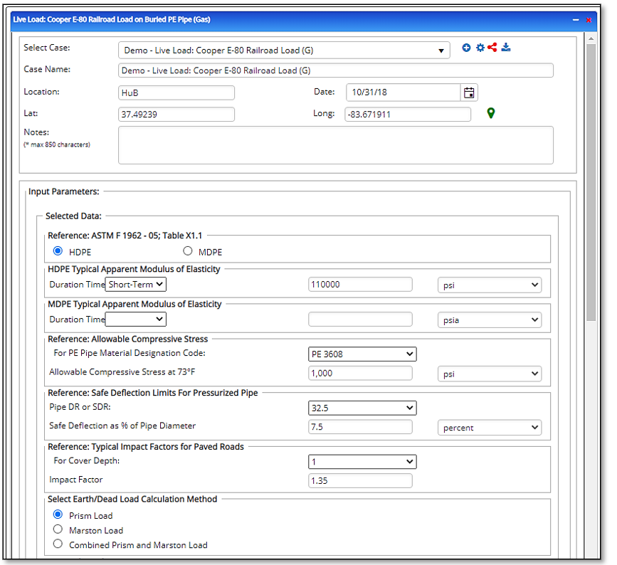
Input Parameters
- To create a new case, click the “Add Case” button
- Select the Live Load: Cooper E-80 Railroad Load on Buried PE Pipe application from the Polyethylene Pipe – Design & Stress Analysis module list.
- Enter Case Name, Location, Date and any necessary notes.
- Fill out all required fields.
- Make sure the values you are inputting are in the correct units.
- Click the CALCULATE button.
- Reference: ASTM F 1962
- HDPE Typical Apparent Modulus of Elasticity
- Duration Time
- Reference: Allowable Compressive Strength
- For PE Pipe Material Designation Code:
- Reference: Safe Deflection Limits for Pressurized Pipe
- Pipe DR/SDR
- Reference: Typical Impact Factor for Paved Road
- Depth of Cover
- Select Earth/Dead Load Calculation Method
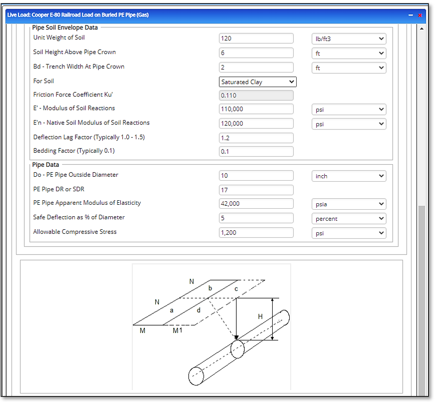
- Pipe Soil Envelope Data
- Unit Weight of Soil
- Soil Height above Pipe Crown
- Bd – Trench Width at Pipe Crown
- For Soil:
- Friction Force Coefficient Ku
- E’ – Modulus of Soil Reaction
- E’n- Native Soil Modulus of Soil Reaction
- Deflection Lag Factor (Typically 1.0 – 1.5)
- Bedding Factor (Typically 0.1)
- Pipe Data
- Do – PE Pipe Outside Diameter
- PE Pipe DR or SDR
- PE Pipe Apparent Modulus of Elasticity
- Safe Deflection as % of Diameter
- Allowable Compressive Stress
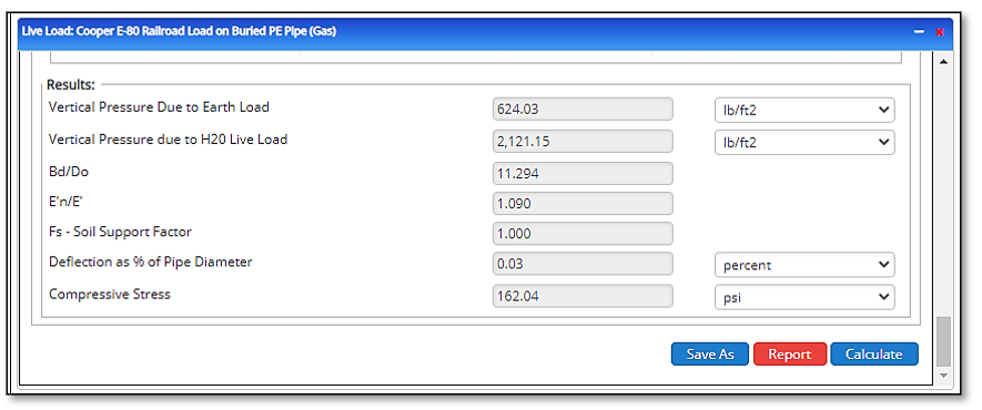
Outputs/Reports
- View the results.
- If an input parameter needs to be edited be sure to hit the CALCULATE button after the change.
- To SAVE, fill out all required case details then click the SAVE button.
- To rename an existing file, click the SAVE As button. Provide all case info then click SAVE.
- To generate a REPORT, click the REPORT button.
- The user may export the Case/Report by clicking the Export to Excel/PowerPoint icon.
- To delete a case, click the DELETE icon near the top of the widget.
- Vertical Pressure due to Earth Load
- Vertical Pressure due to Cooper E-80 Load
- Bd/Do
- E’n/E
- Fs – Soil Support Factor
- Deflection as % of Pipe Diameter
- Compressive Stress
Related Links
Table of Contents
Table of Pages
Table of Contents
- Pipeline HUB User Resources
- AC Mitigation PowerTool
- API Inspector's Toolbox
- Horizontal Directional Drilling PowerTool
- Crossings Workflow
- Hydrotest PowerTool
- Pipeline Toolbox
- Encroachment Manager
- PRCI AC Mitigation Toolbox
- PRCI RSTRENG
- RSTRENG+
- Ad-hoc Analysis
- Database Import
- Data Availability Dashboard
- ESRI Map
- Report Builder
- Crossings Workflow
- Hydrotest PowerTool
- Investigative Dig PowerTool
- Hydraulics PowerTool
- External Corrosion Direct Assessment Procedure - RSTRENG
- Canvas
- Definitions
- Pipe Schedule and Specifications Tables