

Technical Toolboxes Support Wiki
HAVE A SUPPORT QUESTION?
- 7136300505
Pull Force and Installation Stresses Vertical
When pipes are installed by HDD, they often experience high tension loads, severe bending, and external fluid pressures. Often these installation loads are more severe than the design service loads. When selecting the appropriate pipe materials for an HDD installation, the designer must consider the pipe properties as well as the borehole profile. These two factors should be considered together in order to choose the best material and profile so that the pipeline can be installed and operated without risk of damage. To ensure that the material and bore-hole profile are suitable for the proposed application, the installation, operational, and combined loads and stresses are analyzed.
Pipe Weight in Air:
𝑃𝑖𝑝𝑒𝑤𝑒𝑖𝑔ℎ𝑡 = 10.68 (𝐷 – 𝑡)𝑡
𝑃𝑖𝑝𝑒𝑤𝑒𝑖𝑔ℎ𝑡 – Weight of the pipe (lbs/ft)
D – Pipe Outside Diameter (inch)
t – Pipe Wall Thickness (inch)
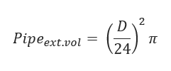
Pipe Exterior Volume:
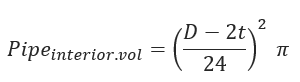
Pipe Interior Volume:
Weight of Water in pipe:
(to be calculated only if the pipe is filled with water)
𝑊𝑎𝑡𝑒𝑟𝑃•𝑤𝑒𝑖𝑔ℎ𝑡 = 𝑃𝑖𝑝𝑒𝑖𝑛𝑡𝑒𝑟𝑖𝑜𝑟 • 𝑣𝑜𝑙 ∗ 𝑊𝑤𝑒𝑖𝑔ℎ𝑡
Wweight – Weight of water (lb/ft3)
Displaced Mud Weight:
𝐷𝑖𝑠𝑝𝑙𝑎𝑐𝑒𝑚𝑢𝑑𝑊𝑒𝑖𝑔ℎ𝑡 = 𝑃𝑖𝑝𝑒𝑒𝑥𝑡•𝑣𝑜𝑙𝑚𝑢𝑑𝑤𝑡
mudwt = Weight of mud (lb/gal)
Effective Weight of Pipe:
𝑊𝑆 = 𝑃𝑖𝑝𝑒𝑤𝑒𝑖𝑔ℎ𝑡 + 𝑊𝑎𝑡𝑒𝑟𝑃•𝑤𝑒𝑖𝑔ℎ𝑡 − 𝐷𝑖𝑠𝑝𝑙𝑎𝑐𝑒𝑚𝑢𝑑𝑊𝑒𝑖𝑔ℎ𝑡
Straight section A-B
Friction from Soil:
𝑓𝑟𝑖𝑐2 = 𝑊𝑆𝐿1𝑐𝑜𝑠𝜃𝑆1𝜇𝑆𝑜𝑖𝑙
𝐿1 – Length of the straight section 1
𝜃𝑆1 – Angle in degrees from horizontal for straight section 1
𝜇𝑆𝑜𝑖𝑙 – Average coefficient of friction between pipe and soil. The recommended value is between .21-.3 (Maidla)
Drag Forces from Mud:
𝐷𝑟𝑎𝑔2 = 𝜋𝐷𝐿1𝜇𝑚𝑢𝑑
μmud – Fluid drag coefficient for steel tube pulled through bentonite mud
Tension on Section:
∆𝑇2 = |𝑓𝑟𝑖𝑐2| + 𝐷𝑟𝑎𝑔2 − 𝑊𝑠𝐿1𝑠𝑖𝑛𝜃𝑠1
Cumulative Pull Load:
𝑇2 = ∆𝑇2 + 𝑇1
T1 – Pull back as the pipe enters the drill hole (lbf)
Curved Section B-C
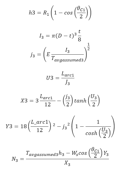
(based on Roark’s solution for elastic beam deflection)
θC1 – Angle in degrees from horizontal for curved section 1
R1 – Radius of curvature of curve section 1 (ft)
Larc1 – Length of curved section 1(ft)
E – Young’s Modulus (psi)
Friction from Soil:
𝑓𝑟𝑖𝑐 = |𝑁3𝜇𝑆𝑜𝑖𝑙|
Drag Forces from Mud:
𝐷𝑟𝑎𝑔3 = 𝜋𝐷𝐿𝑎𝑟𝑐1𝜇𝑚𝑢𝑑
Tension on Section:

Cumulative Pull Load:
𝑇3 = ∆𝑇3 + 𝑇2
Straight Section C-D
Friction from Soil:
𝑓𝑟𝑖𝑐4 = 𝑊𝑆𝐿𝑠𝑐𝑜𝑠𝜃𝑆𝜇𝑆𝑜𝑖𝑙
Ls – Length of straight section between bends (ft)
θs – – Angle in degrees from horizontal for straight section between bends
Drag Forces from Mud:
𝐷𝑟𝑎𝑔4 = 𝜋𝐷𝐿𝑠𝜇𝑚𝑢𝑑
Tension on Section:
∆𝑇4 = |𝑓𝑟𝑖𝑐4| + 𝐷𝑟𝑎𝑔4 − 𝑊𝑠𝐿𝑠𝑠𝑖𝑛𝜃𝑠
Cumulative Pull Load:
𝑇2 = ∆𝑇4 + 3
Curved Section D-E
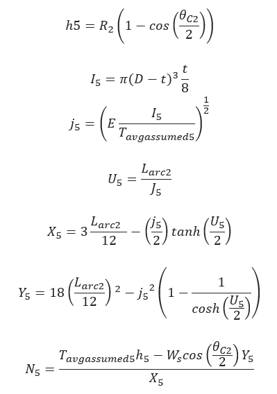
θC2 – Angle in degrees from horizontal for curved section 2
R2 – Radius of curvature of curve section 2 (ft)
Larc2 – Length of curved section 2(ft)
Friction from Soil:
𝑓𝑟𝑖𝑐 = |𝑁3𝜇𝑆𝑜𝑖𝑙|
Drag Forces from Mud:
𝐷𝑟𝑎𝑔3 = 𝜋𝐷𝐿𝑎𝑟𝑐2𝜇𝑚𝑢𝑑
Tension on Section:
Cumulative Pull Load:
𝑇3 = ∆𝑇3 + 𝑇2
Straight Section E-F
Friction from Soil:
𝑓𝑟𝑖𝑐6 = 𝑊𝑆𝐿2𝑐𝑜𝑠𝜃𝑆2𝜇𝑆𝑜𝑖𝑙
Drag Forces from Mud:
𝐷𝑟𝑎𝑔6 = 𝜋𝐷𝐿2𝜇𝑚𝑢𝑑
Tension on Section:
∆𝑇6 = |𝑓𝑟𝑖𝑐6| + 𝐷𝑟𝑎𝑔6 + 𝑊𝑠𝐿1𝑠𝑖𝑛𝜃𝑠12 – Length of the straight section 2
θS2 – Angle in degrees from horizontal for straight section 2
Cumulative Pull Load:
𝑇6 = ∆𝑇6 + 𝑇5
Total pull load of the pipe:
𝑇𝑡𝑜𝑡𝑎𝑙 = ∆𝑇2 + ∆𝑇3 + ∆𝑇4 + ∆𝑇5 + ∆𝑇6
Ttotal – Total pull load of the pipe (lbf)
Maximum Pull Force, F:
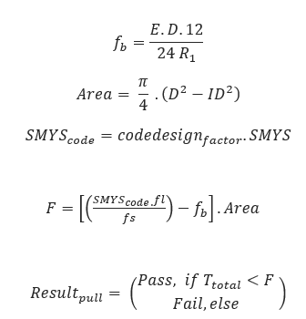
ID – Internal Pipe Diameter (inch)
fs – Safety Factor
F – Maximum pull force (lbf)
Tensile Stress at a Point:
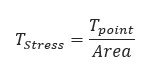
Allowable Tensile Stress:
𝑇𝑆𝑡𝑟𝑒𝑠𝑠•𝑎𝑙𝑙𝑜𝑤 = 0.9𝑆𝑀𝑌𝑆
Bending Stress at a point:
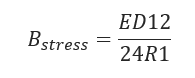
Allowable Bending Stress:
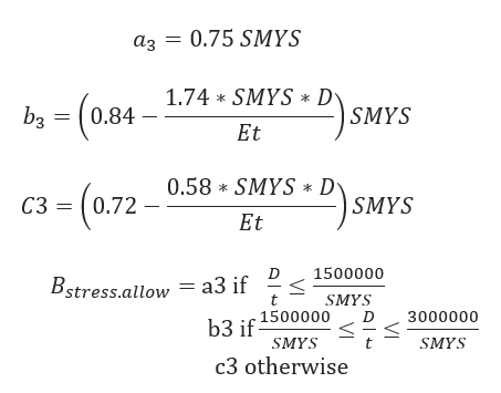
Hoop Stress at a point:
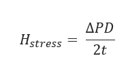
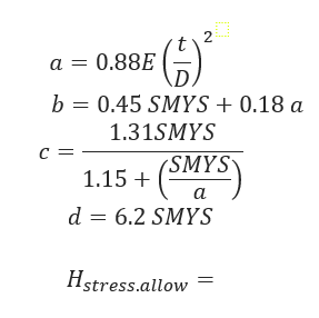
Allowable Hoop Stress:
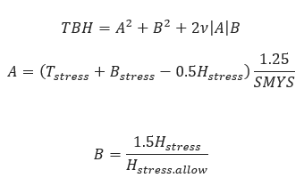
Unity Check – Tensile and Bending Stress:

Unity Check – Tensile, Bending & Hoop Stress:
Input Parameters
Drill Path/Borehole Design*: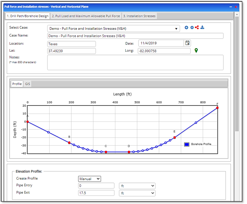
- Elevation Profile
- Pipe Entry (ft)
- Pipe Exit (ft)
- Downslope: Straight Section A – B
- Pipe Entry Angle A – B [degree]
- Measured Length [ft]
- Downslope: Curved Section B – C
- Bend Angle B – C [degree]
- Radius of Curvature B – C [ft]
- Measured Length [ft]
- Straight Section C – D
- Horizontal Angle[degree]
- Measured Length [ft]
- Downslope: Curved Section D – E HDDPT Steel
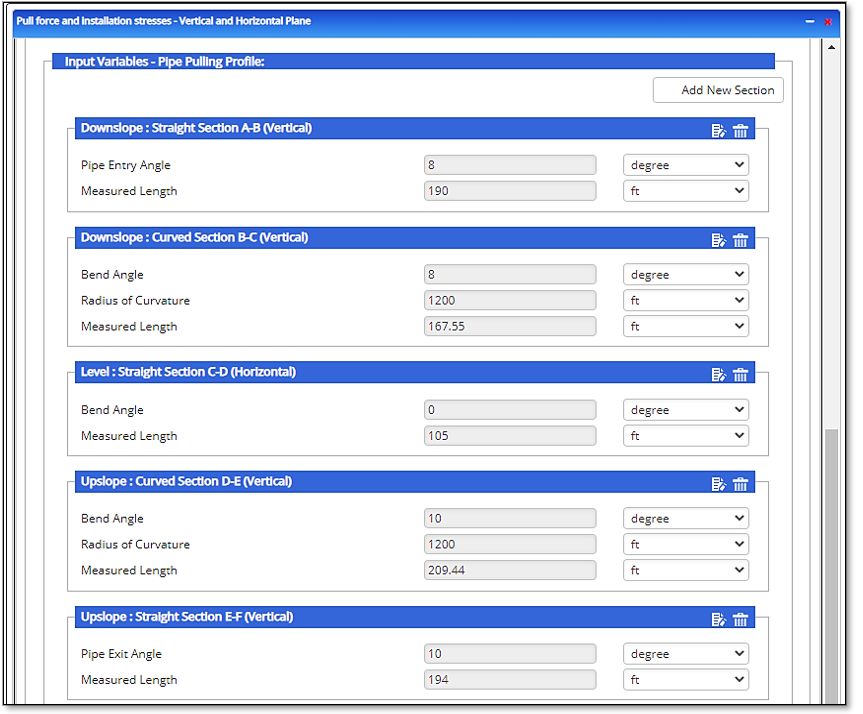
- Horizontal Angle[degree]
- Radius of Curvature D – E
- Measured Length [ft]
- Straight Section E – F
- Bend Angle[degree]
- Measured Length [ft]
- Upslope: Curved Section F – G
- Bend Angle F – G [degree]
- Radius of Curvature F – G [ft]
- Measured Length [ft]
- Upslope: Straight Section G –H
- Bend Angle G – H [degree]
- Radius of Curvature G – H [ft]
- Measured Length [ft]
- Upslope: Straight Section H- I
- Pipe Exit Angle H – I [degree]
- Measured Length [ft]
*The design changes based on borehole design (section configuration)
Pull Load and Maximum Allowable Pull Force:
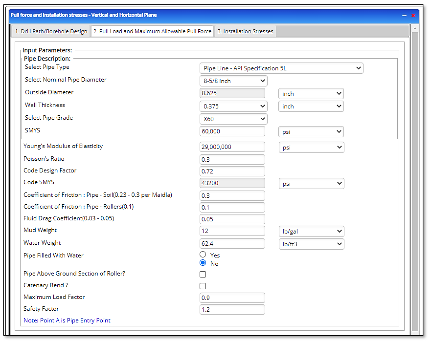 Pipe Outside Diameter (in)
- Pipe Wall Thickness(in)
- Pipe Grade
- SMYS – Specified Minimum Yield Strength(psi)
- Poisson’s Ratio
- Young’s Modulus of Elasticity(psi)
- Code Design Factor
- Code SMYS
- Coefficient of Friction: Pipe – Soil (0.21 – 0.3)
- Coefficient of Friction: Pipe – Rollers (0.1)
- Fluid Drag Coefficient (0.03 – 0.05) (psi)
- Mud Weight (lbs./gal)
- Water Weight(lbs./ft3)
- Pipe Filled with Water:
- Pipe Above Ground Section of Roller?
- Pipe Section Above Ground Section on Rollers (ft)
- Angle of Pipe Above Ground on Rollers (°)
- Maximum Load Factor
- Safety Factor
- Note: Point A is Pipe Entry Point
Outputs/Reports
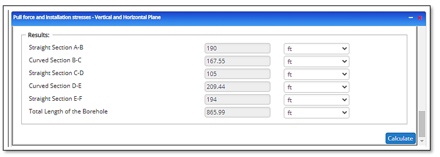
- Straight Section A-B (ft)
- Curved Section B-C (ft)
- Straight (Downslope) Section C-D (ft)
- Curved Section D-E (ft)
- Straight Section E-F (ft)
- Total Length of the Borehole (ft)
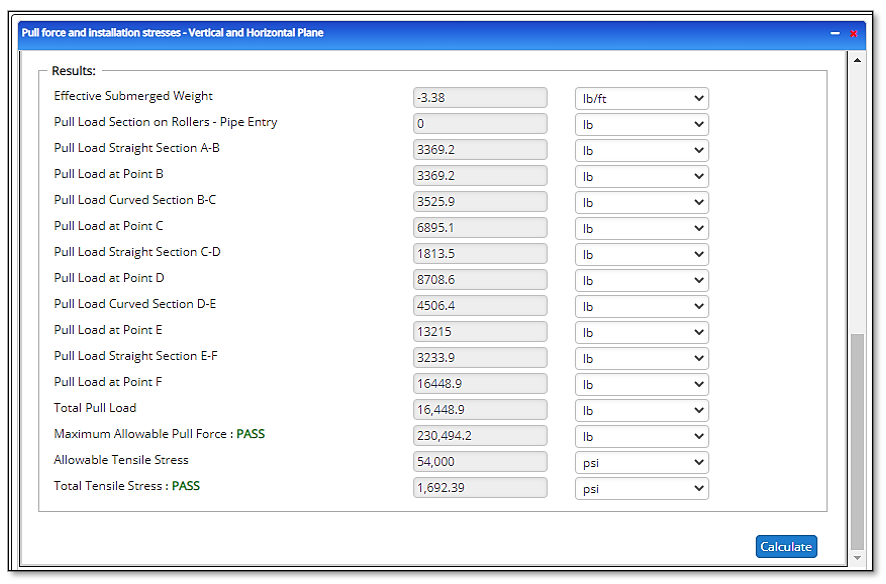
- Effective Submerged Weight (lb./ft)
- Pull Load Section on Rollers (lb)
- Pull Load Straight Section A-B (lb)
- Pull Load at Point B (lb)
- Pull Load Curved Section B-C (lb)
- Pull Load at Point C (lb)
- Pull Load Straight (Downslope) Section C-D (lb)
- Pull Load at Point D (lb)
- Pull Load Curved Section D-E (lb)
- Pull Load at Point E (lb)
- Pull Load Straight Section E-F (lb)
- Total Pull Load at Point F (lb)
- Maximum Allowable Pull Force (lb)
- Allowable Tensile Stress (psi)
- Total Tensile Stress (psi)
Pass/Fail:
Select Point of Interest (B)
- Tensile Stress(psi)
- Allowable Tensile Stress(psi)
- Bending Stress(psi)
- Allowable Bending Stress(psi)
- Hydrostatic Mud Pressure(psi)
- External Hoop Stress(psi)
- Allowable Elastic Hoop Buckling
- Combined Load Interaction at Point
- Unity Check: Tensile and Bending
- Unity Check: Tensile, Bending, and External Hoop
Select Point of Interest (C)
- Tensile Stress(psi)
- Allowable Tensile Stress(psi)
- Bending Stress(psi)
- Allowable Bending Stress(psi)
- Hydrostatic Mud Pressure(psi)
- External Hoop Stress(psi)
- Allowable Elastic Hoop Buckling
- Combined Load Interaction at Point
- Unity Check: Tensile and Bending
- Unity Check: Tensile, Bending, and External Hoop
Select Point of Interest (D)
- Tensile Stress(psi)
- Allowable Tensile Stress(psi)
- Bending Stress(psi)
- Allowable Bending Stress(psi)
- Hydrostatic Mud Pressure(psi)
- External Hoop Stress(psi)
- Allowable Elastic Hoop Buckling
- Combined Load Interaction at Point
- Unity Check: Tensile and Bending
- Unity Check: Tensile, Bending, and External Hoop
Select Point of Interest (E)
- Tensile Stress(psi)
- Allowable Tensile Stress(psi)
- Bending Stress(psi)
- Allowable Bending Stress(psi)
- Hydrostatic Mud Pressure(psi)
- External Hoop Stress(psi)
- Allowable Elastic Hoop Buckling
- Combined Load Interaction at Point
- Unity Check: Tensile and Bending
- Unity Check: Tensile, Bending, and External Hoop
Select Point of Interest (F) 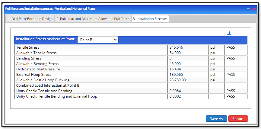
- Tensile Stress(psi)
- Allowable Tensile Stress(psi)
- Bending Stress(psi)
- Allowable Bending Stress(psi)
- Hydrostatic Mud Pressure(psi)
- External Hoop Stress(psi)
- Allowable Elastic Hoop Buckling
- Combined Load Interaction at Point
- Unity Check: Tensile and Bending
- Unity Check: Tensile, Bending, and External Hoop
Related Links
Table of Contents
Table of Pages
- Pipeline HUB User Resources
- AC Mitigation PowerTool
- API Inspector's Toolbox
- Crossings Workflow
- Horizontal Directional Drilling PowerTool
- Hydrotest PowerTool
- Pipeline Toolbox
- PRCI AC Mitigation Toolbox
- PRCI RSTRENG
- RSTRENG+
- Ad-hoc Analysis
- Database Import
- Data Availability Dashboard
- ESRI Map
- Report Builder
- Crossings Workflow
- Hydrotest PowerTool
- Investigative Dig PowerTool
- Hydraulics PowerTool
- External Corrosion Direct Assessment Procedure - RSTRENG
- Canvas
- Definitions
Technical Toolboxes
Technical Toolboxes is a leading provider of integrated desktop and cloud-based pipeline software, online resources, and specialized training for pipeline engineering professionals worldwide. We deliver oil and gas industry training courses covering a breadth of topics with industry-recognized instructors. Compare the performance that Technical Toolboxes technology and training can make in pipeline engineering performance and you’ll see a measurable difference. Our fit-for-purpose pipeline engineering software platform will help you reduce risk, lower the total cost of operations, and accelerate project schedules. Hundreds of companies rely on our certified, industry-standard technology to enhance their pipeline engineering performance.
Contact
Technical Toolboxes
3801 Kirby Drive, Suite 520
Houston, TX 77098
Toll Free: (866) 866-6766
Phone: (713) 630-0505
Fax: (713) 630-0560
[email protected]
© 2021 Technical Toolboxes All Rights Reserved | Privacy Policy | Terms of Use