
Introduction
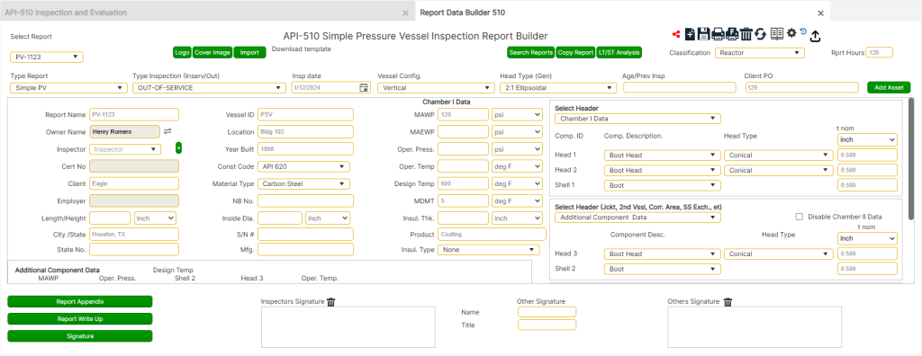
The API 510 Inspection Report Builder provides tools for preparing and organizing pressure vessel inspection reports. It includes modules to guide users through data entry, calculations, and report-building processes, ensuring compliance with API 510 standards.
This tool is designed to streamline the creation of detailed and professional inspection reports, providing a systematic approach to managing key components such as base page data, appendices, corrosion monitoring records, AutoCAD drawings, and write-up recommendations.
Accessing the Tool
To access the API 510 Inspection Report Builder, follow these steps:
Setting Up Reports
- From the base page, choose [API 510 PV Insp.].
- Click on the [Report Builder] button at the bottom of the page.
- Choose [+] for a new report or [Select Report] from the dropdown menu.
- For a new report, enter a unique “Report No.” and select the type of report:
- Simple PV Report: Select if the pressure vessel is designed for internal pressure only. Includes vertical and horizontal drums, heat exchangers, towers, and reactor vessels with half-pipe or dimpled jackets.
- Complex PV Report: Select if the pressure vessel is designed for both internal and external pressures, such as jacketed vessels or any vessels operating under a vacuum. Includes jacketed vessels, towers, and reactors.
Data Entry and Customization
Begin by entering data in the cells as prompted.
- Numerical Data Requirements:
Ensure all numerical data is entered as raw values without signifiers. For example:- Enter “60” for an inside diameter instead of “60’” or “5ft”.
- For “Nominal Thickness,” values must be entered to the thousandths place (e.g., [0.500]).
- Age/Prev Insp.: Enter the inspection age as a number (e.g., 9, 20, 34) instead of a date. This value is critical for calculating corrosion rates and must correspond with the “Nominal Thickness” value.
- Customization Options:
Cells with a [ * ] button allow users to add custom entries to dropdown menus for fields such as Inspector or Service. These additions are saved for future use.
Handling Two-Chamber Vessels
The base page is configured to handle data for two-chamber vessels:
- Primary Chamber: Labeled as “Main Vessel Data.” This includes the third column in the main data section and the top right box.
- Secondary Chamber: Defaults to “Chamber II Data” and includes the bottom right section and the section below the main data section.
Single-chamber vessels: Use only the primary data cells and mark “Chamber II Data” as “NA.”
Two-chamber vessels: Adjust the nomenclature to reflect the specific application. For example:
- Heat Exchangers: Use “Shell Side Data / Tube Side Data.”
- Jacketed Reactors: Use “Main Vessel Data / Vessel Jacket Data.”
Ensure component arrangements are accurately represented. For heat exchangers with two heads on the Tube Side (TS), enter TS data in the primary cells and Shell Side (SS) data in the secondary cells, or vice versa.
Cover Page Customization
The cover page includes standard introductory text that populates automatically with data from the base page.
The base page also accommodates “distinguishing entries” for components operating under different conditions (e.g., heat exchangers or reactors with dual environments). Default headers like [Main Vessel Data] and [Chamber II Data] can be updated to reflect specific sections (e.g., “Shell Side Data” or “Vessel Jacket Data”). These headers will also appear in component calculations and on the Vessel Data Page.
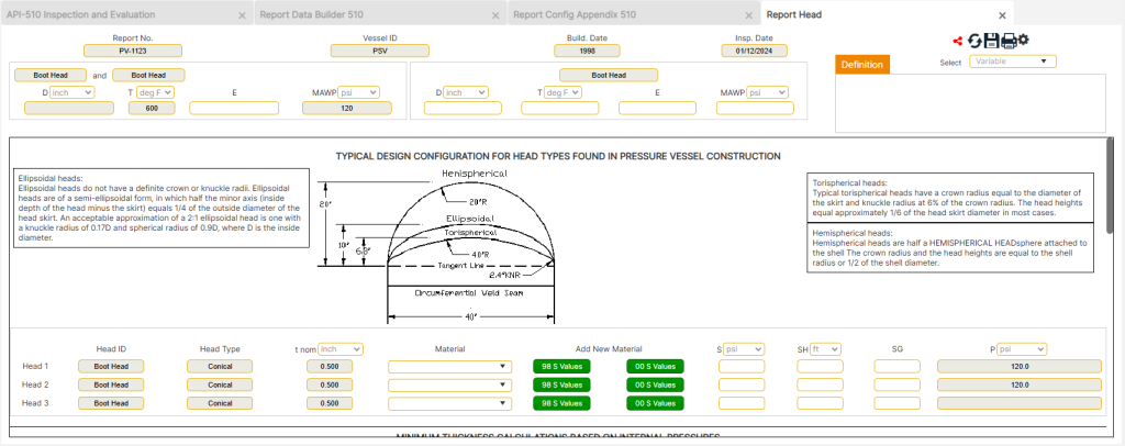
Head Type Configurations
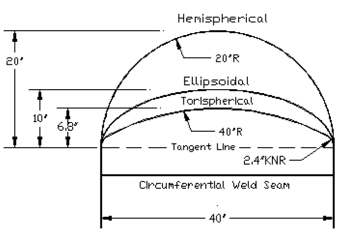
When determining the type of heads, consider the following:
- Ellipsoidal Heads: Semi-ellipsoidal with no definite crown or knuckle radii. Approximation: 2:1 ellipsoidal head = knuckle radius of 0.17D and spherical radius of 0.9D (where D is the inside diameter).
- Torispherical Heads: Crown radius equals the skirt diameter, and the knuckle radius is 6% of the crown radius. Head height is approximately 1/6 of the skirt diameter.
- Hemispherical Heads: Half-sphere heads with crown radius and height equal to the shell radius (or 1/2 of the shell diameter).
Advanced Features
- Adding a Logo: Click on the [Logo] button at the top of the form to upload a company logo. Each report requires the logo to be uploaded individually. Save logos in a dedicated folder, such as “AA Toolbox Support,” for quick access.
- Adding a Signature: Click on the [Signature] button at the bottom of the form to upload a user signature. Note that this must be done individually for each report.

Sharing and Ownership of Reports
- To view shared access, click the group icon (with five people).
- To share a report, the owner must click the linked dots icon and select a user. Use the [Share] button to grant access or the [Make Owner] button to transfer ownership.
- Shared users can view but not edit the report, except for certain appendix functions.
Downloading/Uploading Field Data Sheets
- Downloading Templates: At the top of the Report Base Page, click the [Download Template] link to download Excel and Word templates for data entry and checklists. Save these files in the project folder for the inspection.
- Uploading Templates: After completing the templates, click the [Import] button at the top of the Report Base Page. Select the completed template file and click [Import File] to upload the data into the report.

Saving, Printing, and Copying Reports
- Saving Progress: Always click the [Save] icon before navigating away from the page to ensure no data is lost.
- Printing Options:
- Limited Preview: To print only the first four pages, click the printer icon without a designation.
- Full Report: To print the full report, including appendices, click the printer icon with the “F” designation and select either PDF or Word format.
- Copying Reports: Click on the [Copy Report] button to duplicate an existing report. Enter a new name for the copied report. Note that appendices are not copied and must be created separately.
Once imported, save the report to update the cover text and review or complete any remaining sections.
Report Configuration / Appendix
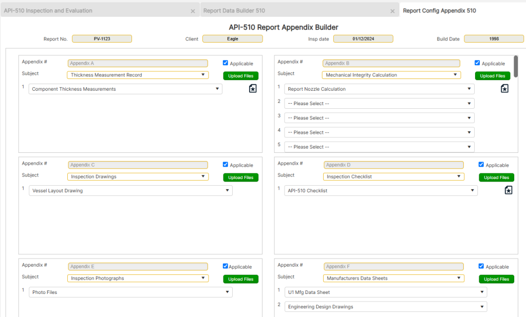
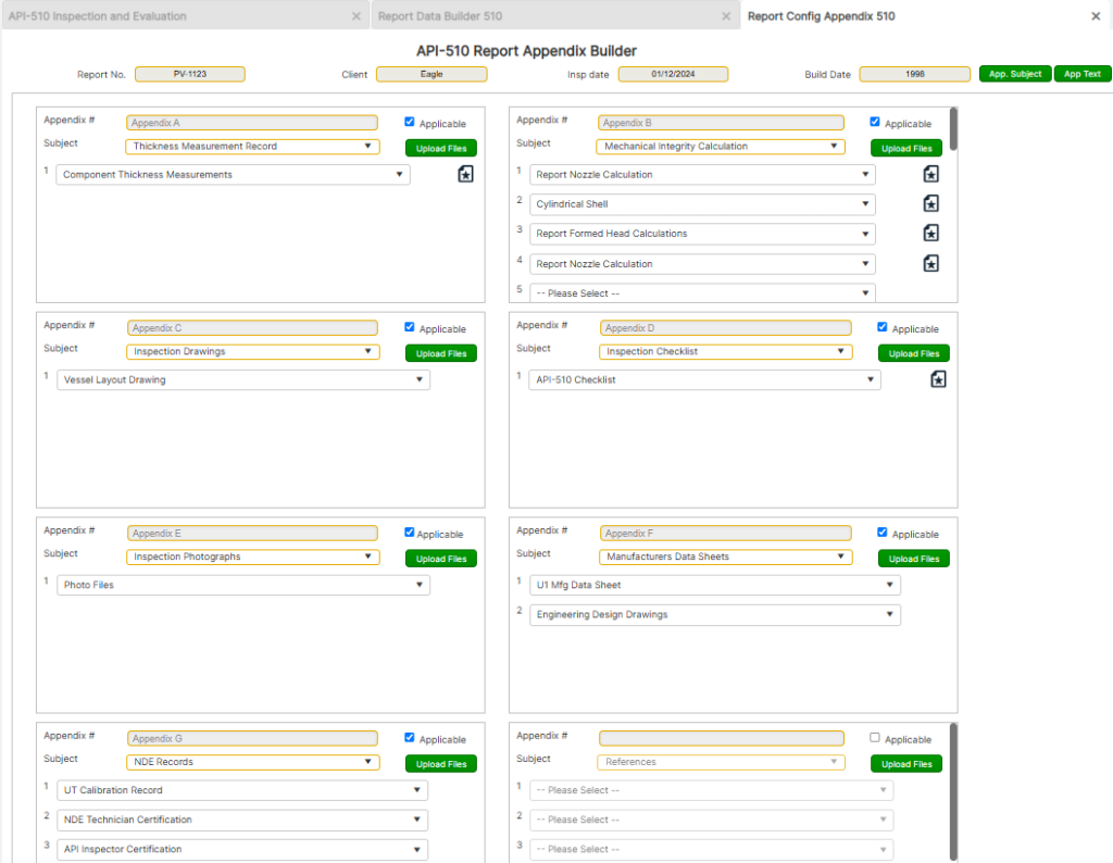
The Report Appendix Builder is a critical tool for creating detailed and customized appendices associated with an API-510 inspection. It provides users with default content that can be tailored to suit the specific requirements of each inspection report.
Accessing the Report Appendix Page
To access the Report Appendix page:
- From the front page, choose [API 510 PV Insp].
- Click on the [Report Builder] button at the bottom of the page.
- Select an existing report from the dropdown menu.
- Click on the [Report Config. / Appendix] button located at the bottom left.
Building the Report Appendices
The Report Appendices automatically populate with the most common appendix subjects associated with an API-510 inspection. This section is divided into separate windows, allowing users to efficiently build and customize their report appendices.
The user should progress systematically from left to right (Appendix A to H) when entering data in subforms. This sequential approach ensures that information is cascaded properly as the report progresses.
Editing and Customizing Appendices
The Report Appendix subjects are preloaded with default text that must be edited to reflect the specific inspection details. Users have the option to:
- Edit Existing Text: Adjust the default text to match the required information.
- Delete and Replace Text: Completely remove the default text and enter custom content as needed.
Each appendix is designed for flexibility, allowing users to adapt the text and structure to align with the unique inspection requirements.
Using Pull-Down Menus for Customization
Each data cell in the appendices includes a pull-down menu with user options. To add additional options to these menus:
- Click on the [App. Subject] or [App. Text] button at the top right corner of the appendix.
- Select the appendix of interest.
- Enter the new subject or text.
- Click Add New Subject/Text.
- Refresh the menu (using the icon with two circular arrows in the upper-right corner) to see the newly added subject or text.
Reviewing and Finalizing Appendices
Before starting data input, the user should thoroughly review each appendix and customize it according to the report’s specific requirements. This includes:
- Selecting or Deselecting Relevant Subjects:
- Use the pull-down menu for the text of interest and select the “Please Select” option to deselect specific text.
- If an entire appendix is not applicable, uncheck the “Applicable” checkbox located in the upper-right corner of the appendix.
Final Steps and Navigation
- Saving Progress: Always click the Save icon before navigating away from any page to ensure that data and changes are not lost.
- Returning to the Base Page: To move back to the Report Base Page, click on the back arrow in the upper-right corner of the screen.
Report Component Corrosion Monitoring location (CML) Record
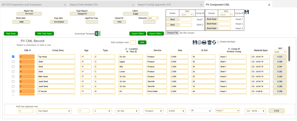
The Corrosion Monitoring Location (CML) Record is a vital tool for capturing and organizing data on pressure vessel components and nozzles. This section allows users to document, manage, and evaluate thickness measurements and material specifications for each monitored location. Proper use of this feature ensures accurate calculations and compliance with API-510 standards.
Accessing the Component CML Data Form
To access the Report Component CML Data Form:
- From the home page, choose [API 510 Insp AST].
- Click on the [Report Builder] button at the bottom of the page.
- Select an existing report from the dropdown menu.
- Click on the [Report Appendix], then select the [Component Thickness Measurements] button (page icon with star in the middle) under Appendix A.
Entering Data in the CML Record
Begin entering data into the PV CML Record data section as prompted.
- Component Disc Entries:
- Entries should reflect a single description per component. For example, all data from “Shell 1” as identified on the Report Builder base page (referenced in the global data box in the upper-right corner) should have “Vessel Shell” entered in this field if “Shell 1” is named as such.
- A pick list of common choices is available and can be expanded by clicking the [*] button next to the column title.
- Age Field:
- The “Age” cell defaults to the age entered on the base page but can be overwritten if the component was replaced and has a different age value.
- Type Field:
- This field designates whether the part is a “Component” or “Nozzle.”
- Components are limited to those entered under Component IDs for Heads and Shells on the base page.
- Nozzles must be accurately categorized, as this distinction affects tml selection and separates types for evaluations.
- A pick list is available for convenience.
Detailed Data Entry Requirements
- C – Location/N – Noz ID Entries:
- Components should describe where thickness measurements (tmls) were taken, such as crown radius, head skirt, or upper shell.
- Nozzles should correspond to the ID system on the inspection drawing (e.g., A, B, C, MW1, N1, etc.).
- Use the pick list provided or add entries using the [*] button.
- Service Column:
- Includes a pick list for common nozzle uses but allows users to input other applicable services. The list can be updated using the [*] button.
- Size Column:
- This column is critical for Nozzle (N-type) entries, as the exact nomenclature is required for extracting stress values in nozzle calculations.
- For Component (C-type) entries, this column may remain blank as it does not affect sub-calculations.
- N-Sch Column:
- Must be filled for Nozzle entries to extract nominal thickness values for calculations.
- The [Pipe Size / Thk Reference per CML] button offers size/thickness information based on selected nozzle sizes.
- C-Comp ID/N-Attach Comp Column:
- For Components: Select the related component from the dropdown.
- For Nozzles: Select the component the nozzle is attached to (e.g., “Head 1” for nozzles on the top head).
- This selection is vital for minimum thickness evaluations.
- Material Spec Column:
- Includes a pick list of commonly used materials.
- If the desired material is not listed, update it via the [Material Spec] option under [Engineering Data].
- For Nozzles, the selected material determines stress values for calculations. Use “CS Unknown (A285 C)” or “CS – A106 B” for unknown specifications, as outlined in API-510.
Data Management and Additional Features
- New/Save/Duplicate/Delete/Print/Back:
- Add CML records one at a time or duplicate an entry for multiple points. Select the checkbox next to the CML of interest and click the duplicate icon.
- CML Data Button:
- Use this to enter thickness readings. Each CML can have up to 4 tml points, with the last entry typically being the lowest reading for corrosion rate and remaining life calculations.
- Actual Plate Thickness (t act):
- Determine the actual thickness to enter for each component. Use the lowest t act value for the component unless a corroded section is evaluated for hoop stress, in which case an average thickness may be used.
Importing and Exporting CML Data
The CML data can be imported/exported using MS Excel.
- Exporting CML Data:
- Click the [Export CML’s] button to export data to an Excel spreadsheet. The spreadsheet can be populated with data from a log file or prepared for import into another report.
- Importing CML Data:
- Click the [Import CML’s] button, attach the Excel file, and click [Import CML’s] to bring the data into the report. The imported data will overwrite any CML with an identical number. Ensure the report number in the spreadsheet matches the target report.
Final Steps and Navigation
- Saving Progress: Always click the Save icon before navigating away to ensure data is not lost.
- Editing Options: Use the [Edit Component Data] or [Edit CML] buttons to modify values or delete erroneous entries.
- Printing: Click the print icon in the upper-right corner to print. Always save the report before previewing or printing.
- Navigation: Click the back arrow at the top-right corner to return to the Appendix page for the next step.
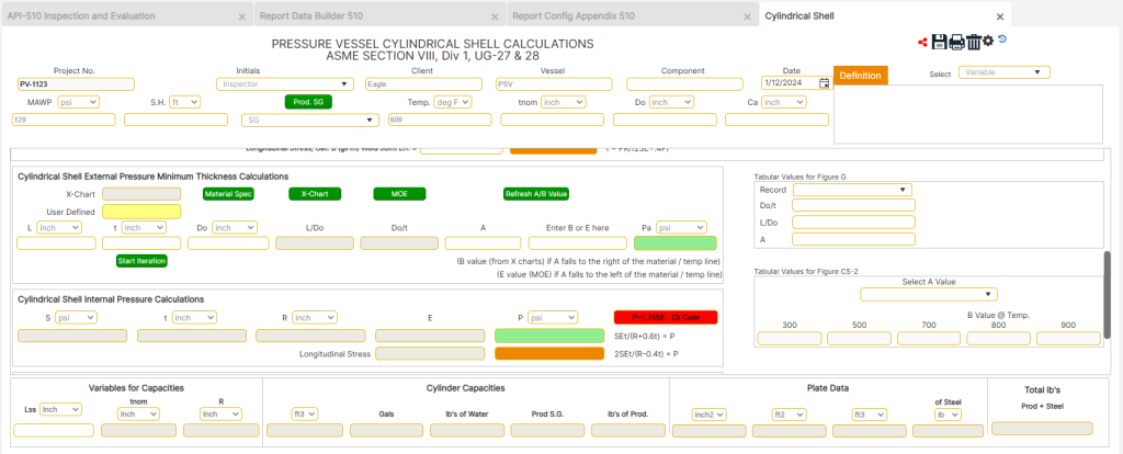
Report Shell Calculations
The Shell Calculations feature provides a structured approach to evaluating the structural integrity of cylindrical pressure vessel components. This section covers both simple and complex pressure vessels and incorporates material properties, operating conditions, and ASME standards to calculate minimum thickness and remaining life. Proper data entry ensures accurate evaluations in accordance with API-510 guidelines.
Accessing Shell Calculations
To access the Cylindrical Shell Calculations page:
- Navigate to the Appendix section from the main interface.
- Select the required report from the dropdown menu.
- Click on the [Shell Calculations] button under the relevant appendix.
Performing Shell Calculations
Primary and Secondary Chamber Data:
- For primary vessels, all cells must be filled. Data is mandatory for every cell related to the primary vessel.
- For secondary chambers, leave cells empty if the chamber is not applicable. If required, ensure all cells for the secondary chamber are completed.
Variable Definitions:
- Variable definitions are available in the table located at the top-right corner of the form.
- Definitions can be accessed via the pull-down menu. Use vertical scrolling to read all the text thoroughly.
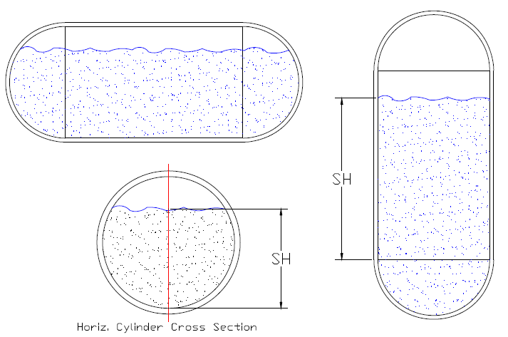
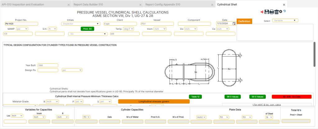
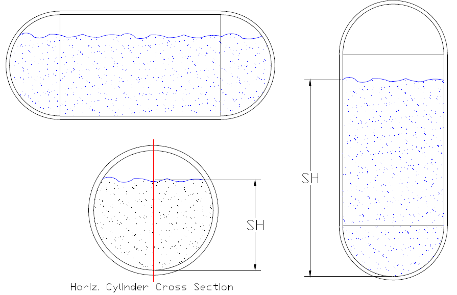
Static Head (SH) and Specific Gravity (SG) Determination
- Static Height (SH):
- For vertical vessels: The SH value typically corresponds to the liquid operating level height (in feet) measured from the bottom shell weld or the bottom of the localized corroded area under evaluation.
- For vessels in gaseous service: Enter 0 for the SH value.
- For horizontal vessels: Enter the height (in feet) from the bottom-most elevation up to the operating liquid level along the diametric centerline of the cylinder’s cross-section.
- Specific Gravity (SG):
- Input the specific gravity of the product in service. If unknown, use the default value of 1.0.
- After entering SH and SG values, click the [Refresh] button. This ensures the form retrieves updated information from external static tables, such as material properties.
Material Selection
- The Material Selection menu accesses a list of materials based on ASME Section II, Part D stress values.
- Select the material of interest from the pull-down menu. Using this menu is essential as it auto-populates the stress (S) value.
- If the desired material is not on the default list, it can be added manually through the [Engineering Data] or [Material] buttons.
Stress (S) Values
- Click the [98 S] button to access 4x safety factor stress values (used for vessels designed prior to 1999).
- Click the [00 S] button to access 3.5x safety factor stress values (used for vessels designed after 1999).
- Users should refer to the manufacturer’s U1 data sheet to ensure the selected stress values correspond to the vessel’s design temperature.
Determining Joint Efficiency (E)
- Joint efficiency (E) values can be obtained from the U1 data sheet or the vessel nameplate.
- Use the [Table 12] button below the first calculation to determine the E value based on configuration and radiographic testing (RT) levels.
- Alternatively, refer to the [Welding] button in the API-510 Inspection Module for a more detailed breakdown of joint efficiency requirements per code.
For Complex Pressure Vessel Reports
Complex PV reports include vessels designed for both internal and external pressures. These require additional data entry and iterative calculations to evaluate external pressure conditions.
- Vacuum Pressure (Vac PSI):
- For vessels rated for full vacuum (noted as “FV” on the U1 data sheet under MAWP), enter a value of 15 psi in the “Vac PSI” field.
- Atmospheric pressure is 14.7 psi (rounded to 15 psi), representing the external pressure on the vessel in a full vacuum.
- External Pressure Source:
- Consider the sum of Design Internal Vacuum (Ext. PSI) and Jacket MAWP (PSI).
- If the jacket does not produce a uniform external force (e.g., half-pipe or dimpled jackets), select the appropriate condition from the pull-down menu.
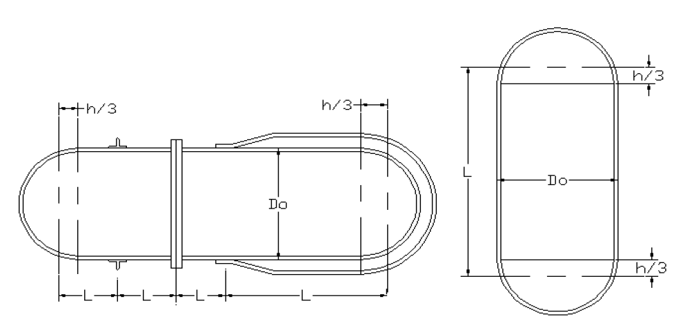
Calculating Minimum Thickness Requirements for External Pressures
Determining minimum thickness requirements for cylindrical components under external pressure is guided by ASME Section VIII, Division 1. The process involves iterative calculations, solving for Pa (external pressure), and referencing external pressure charts (X-Charts). Follow the steps below for detailed guidance:
- Determine the Value of L (Critical Length)
- Definition:
L represents the longest unsupported span along the longitudinal axis of the cylindrical component (e.g., Shell, Nozzle, Boot). - Points of Support:
- Compression rings.
- Flanges.
- Jacket tie-ins.
- One-third of the vessel head measured from the head tangent.
- Reference:
See Figure PV-15 for visual guidance on determining critical length.
- Definition:
- Determine the Starting Value of t (Minimum Thickness)
- Definition:
t is the minimum thickness required to resist external pressures. - Process:
- The program defaults t to the minimum thickness required for internal pressures (E = 1) as the starting point.
- Click the [Start Iteration] button to begin calculations.
- Note: t cannot be less than the value required for internal pressure.
- Definition:
- Reference the Applicable X-Chart
- Purpose:
The X-Chart helps derive external pressure-related parameters based on material properties and component geometry. - Steps:
- The X-Chart Cell will auto-populate based on the selected material.
- To verify material data, click the [Material] button and view specifications.
- To override the default X-Chart, input a new Chart ID in the user-defined cell below the X-Chart.
- Troubleshooting:
If an error message appears, refresh the form by clicking the [Refresh] button and retry accessing the data.
- Purpose:
- Determine Value A
- Definition:
A is derived using the applicable X-Chart (e.g., Figure G, Tabs 1 or 2) and the calculated L/Do and Do/t ratios. - Steps:
- Click the [X-Chart] button.
- Locate L/Do on the Y-axis of the selected X-Chart.
- Move horizontally across the grid until intersecting the Do/t line.
- From the intersection, move vertically down to the X-axis to find A.
- Enter this value in the A Cell.
- Special Note:
For CS materials using X-Charts like CS-2, refer to tabulated values provided next to the formula as an alternative.
- Definition:
- Determine Value B (or E)
- Definition:
B or E is determined from the X-Chart based on the previously calculated A value. - Steps:
- Click the [X-Chart] button and select the appropriate X-Chart tab (e.g., CS-1, CS-2, HA-1).
- Locate A on the X-axis of the chart.
- For Values to the Right of Material/Temperature Line:
- Move vertically upward from A to intersect the material/temperature line.
- Then move horizontally to the Y-axis to find B.
- For Values to the Left of Material/Temperature Line:
- Exit the X-Chart.
- Click the [MOE] button and select the material type.
- Note the value at temperature (e.g., 29 million PSI is entered as 29000000) and input it into the B or E Cell.
- For Values to the Right of Material/Temperature Line:
- Definition:
- Perform Iterative Calculations
- Purpose:
Validate Pa against design parameters and refine thickness values if necessary. - Steps:
- Evaluate the calculated Pa:
- If Pa ≥ Design Pa, the calculation is satisfactory, and the Pa Cell will display a green background.
- If Pa < Design Pa, the calculation is unsatisfactory, and the Pa Cell will turn red.
- If unsatisfactory, incrementally increase t and repeat Steps 2 through 5 until Pa ≥ Design Pa.
- Evaluate the calculated Pa:
- Purpose:
Additional Notes
- Save Progress:
Always click the Save button to record calculations and update the global database. - Validation:
The program provides visual indicators (green or red backgrounds) to ensure the accuracy of calculations. - Integration:
The calculated values integrate with other sections of the report, ensuring cohesion in evaluations.
Remaining Life and Internal MAWP
- Automatic Calculations
- The Remaining Life and Internal MAWP (Maximum Allowable Working Pressure) are automatically calculated by the program. These calculations assess the vessel’s current condition and operational limits.
- User-Defined Adjustments
- Cells for Adjustments: User-defined cells are available for entering alternative values if extenuating conditions require modifications.
- Always click the Save button after making updates or applying user-defined options to ensure all changes are recorded.
- Saving and Global Data Integration
- Prior to exiting or printing, click the Save button to:
- Finalize all calculations.
- Update information in the global database for use in other forms, including head calculations and the Executive Summary TABLE A.
- Prior to exiting or printing, click the Save button to:
- Additional Minimum Required Thickness (tmin) Calculation
- An additional tmin calculation, based on a joint efficiency (E) value of 1, is provided for:
- Nozzle tmin evaluations.
- Reinforcement thickness (tr) calculations.
- Hoop stress calculations for localized corroded areas more than one inch away from weld seams.
- This value is automatically exported to the global database upon saving, ensuring consistency for further evaluations.
- An additional tmin calculation, based on a joint efficiency (E) value of 1, is provided for:
- User-Defined Overrides
- Alternate tmin:
- To use a custom minimum thickness (e.g., nominal minus corrosion allowance), enter the value in the yellow cell under User Defined tmin in the Remaining Life section.
- The entered value will override the calculated tmin.
- Alternate Corrosion Rate:
- If a custom corrosion rate is necessary (e.g., for a new component), input the value in the yellow cell under User Defined Cr in the Remaining Life section.
- This custom value will override the program-calculated corrosion rate and update the remaining life calculation.
- Alternate tmin:
- Flexibility for Unique Scenarios
- These features ensure flexibility in addressing unique vessel conditions and allow for tailored, accurate analysis of the vessel’s structural and operational requirements.
Final Steps and Navigation
- Saving Progress:
- Always save before exiting or printing to ensure all data is stored in the global database.
- Printing Reports:
- Use the print icon in the upper-right corner to preview or print results.
- Ensure all calculations are saved before previewing.
- Global Data Integration:
- Minimum thickness values (tmin) are exported for use in other forms, such as nozzle calculations.
- User-defined tmin or corrosion rates can be entered in the yellow cells to override calculated values.
- Navigation:
- Click the back arrow in the top-right corner to return to the Appendix page for subsequent steps.
Report Head Calculations
The Head Calculations section provides an in-depth methodology for evaluating vessel heads under internal and external pressures, following ASME Section VIII, Division 1. This process requires precise data entry and iterative calculations to determine minimum thickness requirements, remaining life, and integrity under operational conditions.
Accessing the Head Calculations Page
- Navigate to the Head Calculations page from the Appendix page.
- Enter the required data into all white cells as prompted:
- Primary Vessel Cells: Must be fully populated.
- Secondary Chambers: Leave cells blank unless specific “distinguishing entries” are necessary. If required, all secondary chamber cells must be completed.
Static Height (SH) Value
- Definition: The Static Height (SH) is the liquid operating level height (measured in feet) within the vessel, depending on the vessel orientation:
- Vertical Vessels: Measure from the bottom elevation of the head (or the lowest corroded area of interest for localized evaluations).
- Horizontal Vessels: Measure from the bottommost point up to the operating liquid level along the diametric axis.
- Gaseous Service: Set SH to 0 if the vessel operates in gaseous service.
- Enter the Specific Gravity (SG) of the product in the appropriate cell.
- Note: If SG is unknown, use 1.0 in calculations.
Material Selection
- The material selection is based on ASME Section II Part D, allowing access to predefined material stress values.
- Steps:
- Select the material using the dropdown menu.
- This selection auto-populates the stress (S) value.
- If the desired material is not listed, manually input its specifications under the Material cell and associated stress value in the Stress (S) cell.
- Alternatively, add new materials to the database through the [Engineering Data/Material] module.
Stress (S) Values
- Use the [98 S] or [00 S] buttons to access predefined stress tables:
- [98 S]: Reflects a 4x safety factor for vessels designed prior to 1999.
- [00 S]: Reflects a 3.5x safety factor for vessels designed post-1999.
- Select stress values relevant to the vessel design temperature (refer to the Mfg U1 data sheet).
- Note:
- API-510 allows the use of updated stress values for corrosion calculations.
- If calculations yield limited or no remaining life using 98 S values, switch to 00 S values to extend operational time by updating the build date to 2000 and adjusting the PDF report to show the original build date.
Joint Efficiency (E)
- Determine E using the U1 data sheet or vessel nameplate.
- Refer to Table 12 (ASME Section VIII) or click the [Welding] button in the program for guidance on joint efficiency determination.
Special Cases for Seamless Heads:
- E = 1.0: When RT-1 or RT-2 radiographic standards are stamped.
- E = 0.85: When radiography does not meet RT-1 or RT-2 standards, or for specific weld types listed in Table UW-12.
Sidebar:
- Many older pressure vessels were designed assuming E = 1 for seamless heads, regardless of radiographic testing standards.
Complex Pressure Vessel Reports
- Additional data entry is required for vessels rated for full vacuum (FV) in the MAWP line:
- Enter 15 PSI in the Vac PSI field to account for full vacuum conditions.
- The External Pressure Source field accounts for the combined external forces from Design Int. Vacuum and Jacket MAWP (if applicable).
- This applies only to jacketed vessels (e.g., half-pipe, dimpled, or other types) with uniform force distribution over the shell.
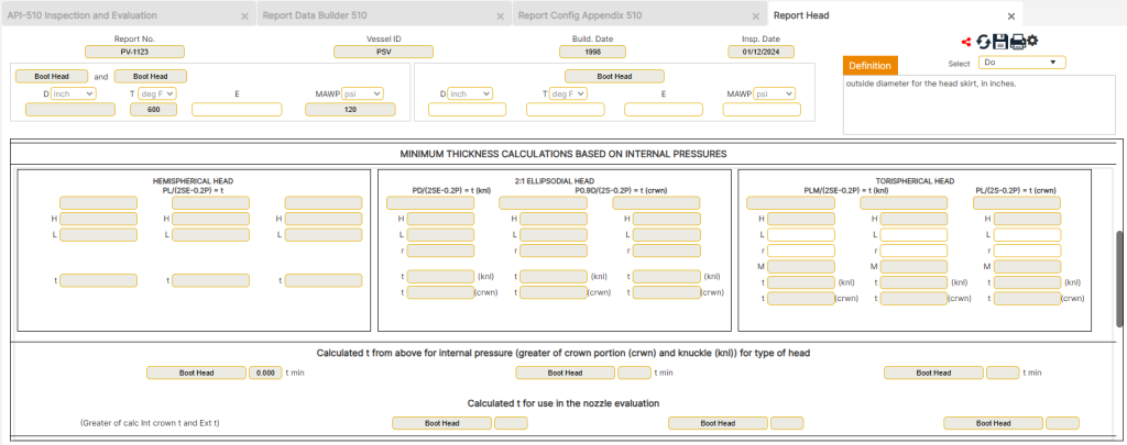
Minimum Thickness Requirements for External Pressures
- Determine L and R Values:
- L: Inside spherical or crown radius of the head (in inches).
- R: Inside knuckle radius (in inches).
- Automatic Calculation: These values are auto-determined unless the head type is torispherical, in which case refer to the U1 data sheet.
- Set Starting Thickness (t):
- Definition:
- t: Minimum thickness (tmin) required for the vessel component to resist external pressures.
- Process:
- Click the [Start Iteration] button above the “t” variable in the external calculation boxes for Head 1.
- The program will default to the tmin value required for internal pressures (E = 1) as the starting point.
- Important Note:
- tmin cannot be less than the thickness required for internal pressure.
- Avoid clicking the [Start Iteration] button again after the iteration process has started, as this action will reset the starting thickness.
- Definition:
- Reference the Applicable X-Chart:
- The program auto-populates the X-Chart cell based on the material selection.
- Reference the Applicable X-Chart
- Purpose:
- The X-Chart determines external pressure-related parameters based on material properties and component geometry.
- Steps:
- The X-Chart Cell will auto-populate based on the material selected.
- To verify material data, click the [Material] button to view detailed specifications.
- If necessary, override the default X-Chart by inputting a new Chart ID in the user-defined cell below the X-Chart.
- Troubleshooting:
- If an error message appears, refresh the form by clicking the [Refresh] button and retry accessing the data.
- Determine Value B (or E):
- Definition:
- B (or E): A critical value derived from the X-Chart, dependent on the material properties and design temperature.
- Steps:
- Click the [X-Chart] button and navigate to the appropriate X-Chart tab (e.g., CS-1, CS-2, HA-1).
- Locate the A value on the X-axis of the chart.
- If A falls to the right of the Material/Temperature Line:
- Move vertically upward from the A value to intersect the material/temperature line.
- From this point, move horizontally to the Y-axis to find B.
- Record this value and input it into the B Cell.
- If A falls to the left of the Material/Temperature Line:
- Close the X-Chart forms.
- Click the [MOE] button and select the appropriate material type.
- Note the modulus of elasticity value at the operating temperature (values are in millions of PSI; e.g., 29 million PSI is entered as 29000000).
- Input this value into the B or E Cell.
- If A falls to the right of the Material/Temperature Line:
- Special Note:
- For CS materials with X-Charts like CS-2, use the provided tabulated values as an alternative to graphical interpolation.
- Definition:
- Perform Iterative Calculations:
- Purpose:
- Pa ≥ Design Pa: Satisfactory; Pa cell displays a green background.
- Pa < Design Pa: Unsatisfactory; Pa cell displays a red background.
- Validate Pa (calculated external pressure) against design parameters and refine thickness values through iterations if necessary.
- Steps:
- Evaluate the calculated Pa:
- If Pa ≥ Design Pa:
- The results are satisfactory, and the Pa Cell will display a green background.
- If Pa < Design Pa:
- The results are unsatisfactory, and the Pa Cell will display a red background.
- If Pa ≥ Design Pa:
- Evaluate the calculated Pa:
- For unsatisfactory results:
- Incrementally increase the t value.
- Repeat Steps 2 through 4 until Pa ≥ Design Pa.
- Purpose:
Saving Calculations and Using User-Defined Overrides
To ensure all calculations are accurately processed and updated within the global database, follow these steps:
- Save Calculations to the Global Database
- Click the Save button at the top of the form to confirm that all newly entered or updated information is stored in the global database. This action ensures seamless integration with other sections, such as the head calculations and the Executive Summary TABLE A.
- Automatic Remaining Life and Internal MAWP Calculations
- The program automatically calculates Remaining Life and Internal MAWP based on the provided data.
- These values are critical for determining the integrity and lifespan of the component.
- User-Defined Overrides for Extenuating Conditions
- Updating Calculations: When alternative values are required, user-defined overrides can be applied. Always click the [Update Calcs] button after entering these overrides to recalculate based on the new inputs.
- Additional Minimum Thickness (tmin) Calculations
- To the right of the minimum thickness calculations, an additional tmin calculation is provided. This is based on an E value of 1 and is primarily used for:
- Nozzle Minimum Thickness (tmin) evaluations.
- Reinforcement Thickness (tr value) calculations.
- Hoop Stress Calculations for localized corroded areas that are more than 1 inch away from any weld seam.
- This value is automatically exported to the global database when the Save button is clicked.
- To the right of the minimum thickness calculations, an additional tmin calculation is provided. This is based on an E value of 1 and is primarily used for:
- Overriding Minimum Thickness (tmin)
- When specific circumstances require an alternate tmin value (e.g., using nominal thickness minus corrosion allowance), users can:
- Enter the new tmin in the yellow cell labeled User-Defined tmin under the Remaining Life section.
- This overrides the calculated value and uses the user-defined tmin for subsequent evaluations.
- When specific circumstances require an alternate tmin value (e.g., using nominal thickness minus corrosion allowance), users can:
- Overriding Corrosion Rate
- If an alternate corrosion rate is necessary (e.g., a new component using a previously determined corrosion rate):
- Enter the desired corrosion rate in the yellow cell labeled User-Defined Cr in the Remaining Life section.
- This action overrides the program’s calculated corrosion rate and updates the remaining life accordingly.
- If an alternate corrosion rate is necessary (e.g., a new component using a previously determined corrosion rate):
- Final Validation Before Exiting or Printing
- Before exiting or generating a report, ensure all updates are saved by clicking the Save button.
- This guarantees that all calculations and overrides are correctly applied and recorded in the database.
Final Steps and Navigation
- Print the Report:
- Click the print icon in the upper-right corner to generate a preview or final report.
- Always save progress before printing to reflect all calculations.
- Return to Appendix:
- Use the back arrow at the top-right corner to navigate back to the Appendix page for further actions.
- Ensure Accuracy:
- Verify all entries and calculations before exiting or proceeding to the next section.
- For localized evaluations (e.g., nozzles, corroded areas), additional calculations may be required.
Report Nozzle Calculations
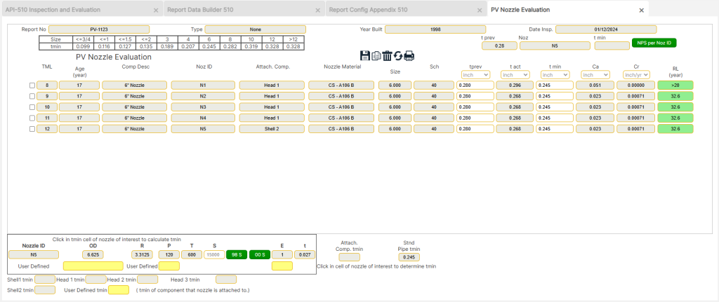
Nozzle calculations are a crucial part of pressure vessel inspections and evaluations, ensuring that nozzles meet minimum thickness requirements for safe operation. This section provides guidance on determining the minimum required thickness (tmin) for nozzles based on ASME Section VIII, UG-45 and UG-27. The calculations consider pipe schedules, connecting shell or head thickness, and high-pressure conditions to determine whether the default or recalculated thickness should be used.
Accessing the Nozzle Calculations Page
- Navigate to the Appendix Page and select Nozzle Calculations to enter the required data.
- The calculations in this section are based on previous data entries and the minimum thickness recommendations outlined in ASME Section VIII, UG-45 for nozzle tmin determination.
Nozzle Thickness Determination
Nozzle minimum thicknesses (tmin) are calculated using the following guidelines:
- Standard Pipe Thicknesses Minus 12.5%
- The nominal pipe thickness is reduced by 12.5% as per industry standards.
- Comparison with the Connecting Shell/Head Thickness
- The minimum thickness is determined by selecting the smaller value between:
- The calculated nozzle thickness.
- The required thickness of the connecting shell or head to which the nozzle is attached.
- The minimum thickness is determined by selecting the smaller value between:
- Special Cases for Large Nozzles or High-Pressure Nozzles
- Nozzles that are large in size or subjected to high pressures require special calculations per ASME Section VIII, Division 1, UG-27, using the formula: PR/SE−0.6P=tPR / SE – 0.6P = tPR/SE−0.6P=t
- If the tmin calculated from this formula is greater than the values from (1) or (2) above, then this new thickness value is used.
Default and User-Defined Thickness Values
- The program automatically enters default values for tprev (previous thickness) and tmin (minimum thickness).
- Users can override these values by simply typing the new thickness in the respective cell above the default value.
- The final calculation at the bottom of the form corresponds to the CML line where the cursor is placed.
Nozzle Pipe Size Reference Tool
- A [NPS per Noz ID] button is provided for quick reference.
- This tool allows users to view Outer Diameter (OD) and pipe schedules/wall thickness for a selected nozzle size.
- Steps to Use the Tool:
- Click on the CML of interest.
- Click on the [NPS per Noz ID] button in the top-right corner.
- A reference table will display the relevant pipe OD, schedules, and wall thicknesses for the selected nozzle size.
- Note that the selection pull-down menu does not function while in this mode.
Final Steps and Navigation
- Saving Data:
- Always click the Save Icon to ensure all changes are updated and stored in the database.
- Printing the Nozzle Calculations Report:
- Click the Print Icon in the upper-right corner to generate a report preview.
- Important: Always save progress before selecting print preview to prevent data loss.
- Returning to the Appendix Page:
- Click the Back Arrow in the upper-right corner to return to the Appendix Page and proceed to the next step.
Extraneous Calculations
Extraneous calculations provide additional evaluation options within the API 510 Inspection Report. These calculations allow users to perform specific analyses outside the standard report structure and integrate them into the final report as needed. This section outlines the process for selecting, accessing, and performing extraneous calculations, ensuring accuracy and proper documentation.
Selecting an Extraneous Calculation
- Navigate to Appendix B:
- Open the Appendix Page from the Report Builder.
- Locate Appendix B, which contains the available extraneous calculations.
- Choose a Calculation of Interest:
- Click on the [-Please Select-] button.
- A drop-down list will appear, displaying all available extraneous calculations.
- Select the desired calculation from the list.
- Access the Selected Calculation:
- Click on the Access Icon (displayed as an icon with a star) to open the selected calculation.
Performing the Calculation
- Enter Required Data:
- Input the necessary data into the available white cells according to the unit system specified on the Report Base Page.
- Follow standard data entry procedures to ensure consistency across the report.
- Review Variable Definitions:
- Most calculations include a variable definition table in the upper-right corner of the form.
- Some calculations may have their variable definitions located at the bottom-left instead.
Integration with the Report
- Once the calculation is completed, it will now be listed in the Appendix.
- The calculation will automatically print in the listed order along with the full API 510 Inspection Report.
Final Steps and Navigation
- Saving Data:
- Always click the Save button before navigating away to ensure the entered data is properly stored.
- Reviewing the Appendix Order:
- Ensure that all selected extraneous calculations appear in Appendix B in the correct order.
- Printing the Report with Extraneous Calculations:
- When generating the full inspection report, the extraneous calculations will print in their listed order within the Appendix section.
- Returning to the Appendix Page:
- Click the Back Arrow in the upper-right corner to return to the Appendix Page and continue with the next steps in the report-building process.
Report AutoCAD PV Inspection Drawings
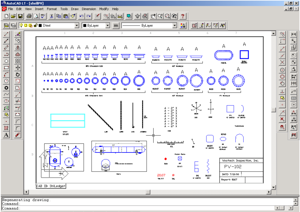
The AutoCAD PV Inspection Drawing process is essential for documenting pressure vessel (PV) inspections with precise, scaled drawings. This section provides detailed steps for accessing, editing, and uploading AutoCAD inspection drawings as part of an API 510 inspection report. Proper adherence to these steps ensures that drawings reflect accurate field data and comply with industry drawing protocols.
Requirements for Using AutoCAD Inspection Drawings
- AutoCAD Software:
- The user must have AutoCAD (1997 or later) installed to utilize this function.
- Field Data and Project Drawings:
- The field data sheet and associated project drawings must be obtained before beginning the process.
Accessing AutoCAD PV Inspection Drawings
- Navigate to the Appendix Page:
- Open the Appendix Page in the Report Builder.
- Locate Appendix C, which contains the AutoCAD PV Inspection Drawings section.
- Select the AutoCAD Inspection Drawing Option:
- Click on the AutoCAD Inspection Drawings icon (page with a star) under Appendix C.
- Save the File:
- Save the AutoCAD file to a project folder for future modifications.
- Print out the Ledger drawing for reference while creating the shell drawing.
Editing the AutoCAD PV Drawing
Once the CAD drawing is open and saved to a project folder, proceed with the following steps while referencing the field data sheets and project drawings:
Step 1: Edit Title Blocks and Report-Specific Text
- Switch to Paper Space (PS) in AutoCAD by typing
PSin the command line. - Modify the title blocks and drawing text to reflect the specific inspection report details:
- Company name
- Inspection date
- Other required text fields per company drawing standards.
Step 2: Insert the Vertical or Horizontal PV Template
- Switch to Model Space (MS) by typing
MSin the command line. - Enter the following AutoCAD commands to insert the appropriate Pressure Vessel (PV) template:
- Command:
INSERT - Enter:
"Vert"(for vertical vessels) or"Horz"(for horizontal vessels) - Insertion Point:
"0,0" - X Scale Factor:
Enter default(or user-defined value if scaling is needed) - Y Scale Factor:
Enter default(or user-defined value if scaling is needed) - Rotation Angle:
Enter default(adjust if necessary)
- Command:
Step 3: Adjust Drawing Scale
- Zoom to Limits by entering:
ZOOM→Limits- (If this does not provide a full view, manually zoom and adjust to an appropriate scale to bring the shell into full view.)
Step 4: Explode and Modify Drawing Components
- Explode the Vertical Block to enable modifications:
- Command:
EXPLODE→ Select the"Vert"block.
- Command:
- Modify the drawing to accurately reflect the design and inspection data of the specific Pressure Vessel (PV) being inspected.
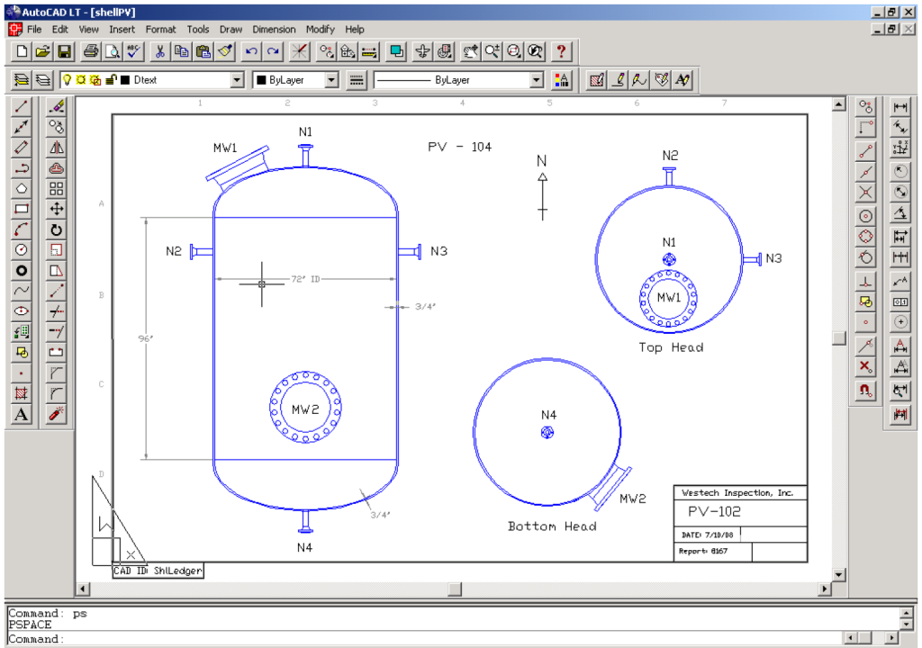
Referencing the Shell Template Drawing
- Use the Shell Template Drawing as a reference for adding scaled blocks, such as:
- Manways
- Nozzles
- Platforms
- Other appurtenances
- Modify Vertical or Horizontal templates as needed to match the actual pressure vessel design.
Uploading AutoCAD Inspection Drawings
Once the inspection drawings are completed and saved as PDFs, follow these steps to upload the files to Appendix C in the report:
- Click the [Choose File] Button:
- Navigate to the folder where the PDF file is saved.
- Select the appropriate AutoCAD inspection drawing file.
- Click the [Upload] Button:
- The selected file will be uploaded to Appendix C.
- Repeat Steps 1-2 for Additional Files:
- Continue uploading multiple attachments as needed for the complete inspection report.
Final Steps and Navigation
- Ensure all modifications are correctly saved before uploading the final inspection drawing.
- Double-check the title blocks to confirm that all report-specific information is correctly entered.
- Verify drawing scale and annotations to ensure accuracy before printing the final AutoCAD PDF file.
- Return to the Appendix Page by clicking the Back Arrow in the upper-right corner to proceed with the next section of the report.
Report PV Checklists
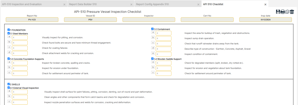
The PV Checklist serves as a systematic verification tool for ensuring that all required inspection elements have been reviewed and documented. This section allows users to mark completed checklist items as part of the API 510 Inspection Report.
Accessing the Report Checklist Section
- Navigate to the Appendix Page in the Report Builder.
- Click on the [Checklist] button under Appendix D.
Completing the Inspection Checklist
- Scroll through the list of inspection items provided in the checklist.
- Mark completed inspection tasks by entering an “X” in the corresponding cell.
- Ensure the “X” is entered in capital letters (i.e., “X” instead of “x”).
- Each entry represents a specific step, verification point, or condition check performed during the inspection process.
Printing and Finalizing the Checklist
- To print the checklist, click the print icon in the upper-right corner.
- This will generate a print preview of the completed checklist.
- Ensure all changes are saved before printing.
- Click the save icon in the upper-right corner before selecting print preview.
- Return to the Appendix Page by clicking the Back Arrow in the upper-right corner.
- This will allow the user to proceed with the next section of the API 510 Inspection Report.
Report Inspection Photograph
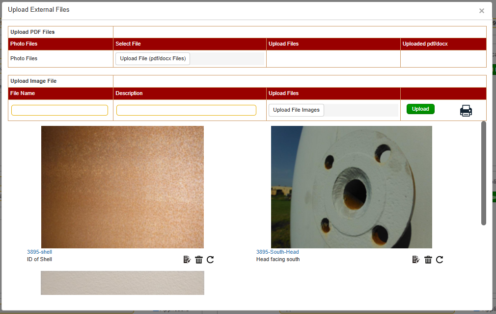
The Inspection Photographs section in the API 510 Inspection Report Builder allows users to develop and upload inspection photographs into a Word document. A link to the File Cabinet is provided to access a pre-designed Word document to aid in this process.
Accessing Inspection Photographs
To access the Inspection Photographs section:
- From the front page, choose [API 510] and click on the [Report Builder] button.
- Select an existing report from the dropdown menu.
- Navigate to the [Appendix Builder] section and click on the [Upload Files] button under Appendix E.
Inspection Photograph Features
Once the Inspection Photographs Appendix is open, complete the following steps:
- Enter caption text in the header space for the photo to be uploaded.
- Click the [Choose File] button and locate the photo you wish to upload.
- Click the [Upload] button to add the photo to the document.
- Repeat steps 1–3 until all photographs have been uploaded.
Final Steps and Navigation
- Save Progress
- Always click the [Save] icon before navigating away from the page to ensure all data and changes are preserved.
- Navigation
- After completing the photograph uploads, click the [Back Arrow] in the upper-right corner to return to the Appendix page and proceed to the next step.
All other Appendices
The remaining appendices in the API 653 Inspection Report Builder allow users to upload additional files, such as PDF attachments, for inclusion in the report. These files provide supplementary data, calculations, or documentation relevant to the inspection.
Accessing Other Appendices
To access the remaining appendices:
- From the front page, choose [API 510] and click on the [Report Builder] button.
- Select an existing report from the dropdown menu.
- Navigate to the [Appendix Builder] section and click on the [Upload Files] button under the appendix of interest.
Appendix Upload Process
Once the Inspection Appendix page is open, complete the following steps:
- Click the [Choose File] button and locate the PDF file you wish to upload.
- Click the [Upload] button to attach the file to the appendix.
- Repeat steps 1–2 until all necessary files are uploaded.
Final Steps and Navigation
- Save Progress
- Always click the [Save] icon before navigating away from the page to ensure all data and changes are preserved.
- Navigation
- After completing file uploads, click the [Back Arrow] in the upper-right corner to return to the Appendix page and proceed to the next step.
Report Write-up and Recommendations
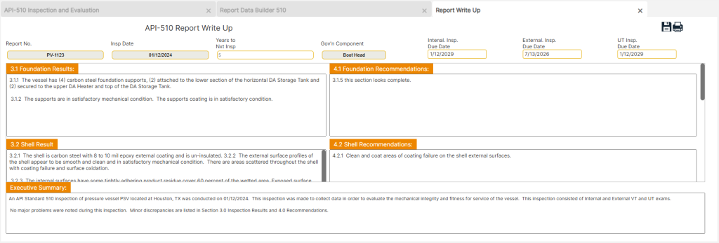
The Write-up and Recommendations section of the API 510 Inspection Report is a critical component for documenting findings and providing professional recommendations based on inspection results. This section enables users to input detailed assessment reports, define inspection intervals, and address component-specific recommendations.
Accessing the Write-up and Recommendations Section
- Navigate to the Base Page in the Report Builder.
- Click on the [Write-up and Recommendations] button under the report’s main menu.
Structuring the Write-up and Recommendations
This section consists of multiple reporting fields, each designed to document specific inspection findings, analysis results, and corrective recommendations.
Editing Default Text
- The write-up and recommendation fields contain default placeholder text that must be edited to reflect specific inspection details.
- Users may either:
- Edit the default text to incorporate findings.
- Delete the default text and input customized recommendations.
Key Data Fields and Inputs
1. Next Inspection Interval and Governing Component
- “Years to Next Insp.”
- This field determines the timeline for the next UT (Ultrasonic Testing) inspection.
- The standard default reference is 10 years for determining corrosion rates unless conditions suggest a different interval.
- Governing Component Identification
- This refers to the component with the least remaining life.
- Governing components typically dictate the next required inspection date based on thickness measurements and projected corrosion rates.
2. UT Results Summary and Recommendations
- This section documents the findings of the ultrasonic thickness (UT) evaluation.
- The summary should outline:
- Key calculation results.
- Any inspection issues related to corrosion, material degradation, or thickness reduction.
- Notable recommendations for corrective actions, maintenance, or further assessments.
3. Executive Summary (ES)
The Executive Summary (ES) provides a high-level overview of critical findings and recommendations.
- Editing the Executive Summary
- This section also contains default placeholder text, which should be:
- Edited to reflect key inspection conclusions.
- Deleted and replaced with custom text if necessary.
- This section also contains default placeholder text, which should be:
- Content Considerations
- The ES should primarily highlight:
- Significant cost implications related to repairs, maintenance, or component replacements.
- Operational limitations resulting from material degradation, compliance issues, or inspection findings.
- Issues documented in the body of the report can be copied and pasted into the ES, with minor refinements for brevity and clarity.
- The ES should primarily highlight:
4. Spell Checking and Finalizing Content
To ensure the accuracy and professionalism of the report:
- Spell Check Process
- Place the cursor within the top left of the write-up text window or highlight the ES text window.
- Press F7 on the keyboard to initiate spell check.
- Each section must be checked separately to ensure correct spelling and grammar.
- Understanding the Executive Summary Display
- The ES does not appear in the Write-up preview page.
- Instead, it is included in the main page preview of the report.
Printing and Saving the Write-up and Recommendations
- To print the write-up and recommendations, click the print icon in the upper-right corner.
- This will generate a preview of the report.
- Ensure all changes are saved before printing.
- Click the save icon in the upper-right corner before selecting print preview.
- Return to the Appendix Page by clicking the Back Arrow in the upper-right corner.
- This will allow the user to proceed with the next section of the API 510 Inspection Report.