
Introduction
This calculator estimates the amount of gas lost when a pipe segment is damaged. It handles two types of damage — a puncture (a hole in the side wall of the pipe) and a complete severance (the pipe cut in two) — and reports the equivalent puncture diameter, the pressure at the break, the volume of gas lost over a specified duration, and the monetary value of that lost gas.
The values calculated by this method are a rough estimate of the maximum gas lost through a punctured or severed line. Many real-world factors are not accounted for — such as resistance at the break from soil or blockages, an irregular shape and/or rough edges of the opening, and pressure loss from normal system flow — so the method tends to overestimate lost gas volume. Always verify the calculated volume against recorded meter readings where practical.
Background
When a pipe line is punctured or severed, the gas will generally vent into the atmosphere, the rate depending on the line pressure. In the unusual case where the line pressure is less than the surrounding pressure — for example, a low-pressure line submerged in water with a static head greater than the line pressure — the gas will not escape and water will instead enter the line. In nearly all other cases, however, once the object causing the damage has been removed, the gas vents to the atmosphere freely. The only exact way to determine the amount lost is through direct measurement, which is usually only possible when the flow is large enough to register as an anomaly on an upstream meter or gate station. This calculator provides alternative methods for estimating gas lost due to a puncture and due to a complete severance.
Puncture
For a puncture, the flow through the damage is assumed to behave similarly to flow through an orifice meter. A puncture in the side wall of a pipe is obviously not identical to a finely machined, sharp-edged orifice, but the similarities are close enough that a suitable estimating formula can be derived from a general orifice meter equation — in this case, the AGA Report No. 3 orifice equations. As implemented, a “puncture” may be a circular hole, a rip or tear, or an irregularly shaped opening.
Because a real puncture is not exactly circular, not sharp-edged, and may have pieces of pipe material protruding into the flow path, a shape factor parameter is included to decrease the computed flow and account for these deviations from ideal orifice behavior. The user is responsible for selecting an appropriate shape factor value. When solving a puncture, the pressure immediately upstream of the puncture is taken to equal the downstream pressure of the supply piping, and the pressure immediately downstream of the puncture is taken to be atmospheric. The downstream supply-piping pressure is found iteratively: the pressure drop across the supply piping is computed for a trial flow rate, and the process repeats until the flow through the orifice and the flow through the supply piping are equal.
As a rule of thumb, if the area of the damage exceeds about 75% of the pipe’s flow area (puncture size greater than about 75% of the pipe diameter), the puncture assumption is no longer valid and the damage should be treated as completely severed.
Severed Line
For a severed line, the line is assumed to be completely cut and the flow unrestricted, with the severed end open to the atmosphere. The flow along the supply route is treated like normal pipe flow: the pipe components are combined, using their equivalent lengths and diameters, into a single equivalent segment. Flow through that equivalent segment is computed using an upstream (inlet) pressure equal to the specified supply pressure and a downstream (outlet) pressure equal to atmospheric pressure for normal flow, or some higher value in the case of choked (sonic) flow.
Equations
GASCalc computes the gas flow rate through a puncture by combining the puncture flow equation below with a selected pipe flow equation, balancing the two with a trial-and-error process. The pipe pressure drop is calculated using the selected pipe flow equation (see the Pipe Flow calculation reference); the puncture flow is treated as flow through a generic circular orifice, derived from the AGA Report No. 3 orifice meter equations. The applicable form depends on whether flow through the puncture is subsonic or sonic (choked).
Subsonic Flow
The subsonic equations apply when the ratio between downstream/upstream pressure is as follows:
\frac{P_2}{P_1} > \left(\frac{2}{k+1}\right)^{\frac{k}{k-1}}\frac{P_2}{P_1} > \left(\frac{2}{k+1}\right)^{\frac{k}{k-1}}
Where:
P1 − Pipe Inlet (Upstream) Pressure, psia
P2 − Pipe Outlet (Downstream) Pressure, psia
k − Specific Heat Ratio, dimensionless
Then:
Q = 685.68 \times D^2 \times \frac{T_B}{P_B} \times \left(\frac{P_1^2 - P_1 P_2}{SG \times T_F}\right)^{0.5} \times Y_1 \times EQ = 685.68 \times D^2 \times \frac{T_B}{P_B} \times \left(\frac{P_1^2 – P_1 P_2}{SG \times T_F}\right)^{0.5} \times Y_1 \times E
Where:
Q − Volumetric Flow Rate at the Specified Base Pressure and Temperature, cfh
D − Inside Diameter Equivalent of the Puncture, inches
TB − Base Temperature, °R
PB − Base Pressure, psia
P1 − Pipe Inlet (Upstream) Pressure, psia
P2 − Pipe Outlet (Downstream) Pressure, psia
SG − Specific Gravity, dimensionless
TF − Average Gas Flowing Temperature, °R
Y1 − Expansion Factor, dimensionless
E − Shape Factor, dimensionless
Y_1 = 1 - \frac{0.41}{k} \left(\frac{P_1 - P_2}{P_1}\right)Y_1 = 1 – \frac{0.41}{k} \left(\frac{P_1 – P_2}{P_1}\right)
Where:
Y1 − Expansion Factor, dimensionless
k − Specific Heat Ratio, dimensionless
P1 − Pipe Inlet (Upstream) Pressure, psia
P2 − Pipe Outlet (Downstream) Pressure, psia
Sonic (Choked) Flow
The choked equations apply when the ratio between downstream/upstream pressure is as follows:
\frac{P_2}{P_1} \leq \left(\frac{2}{k+1}\right)^{\frac{k}{k-1}}\frac{P_2}{P_1} \leq \left(\frac{2}{k+1}\right)^{\frac{k}{k-1}}
Where:
P1 − Pipe Inlet (Upstream) Pressure, psia
P2 − Pipe Outlet (Downstream) Pressure, psia
k − Specific Heat Ratio, dimensionless
Q = 685.68 \times D^2 \times \frac{T_B}{P_B} \times P_1 \times \left(\frac{1 - \left(\frac{2}{k+1}\right)^{\frac{k}{k-1}}}{SG \times T_F}\right)^{0.5} \times Y_1 \times EQ = 685.68 \times D^2 \times \frac{T_B}{P_B} \times P_1 \times \left(\frac{1 – \left(\frac{2}{k+1}\right)^{\frac{k}{k-1}}}{SG \times T_F}\right)^{0.5} \times Y_1 \times E
Where:
Q − Volumetric Flow Rate at the Specified Base Pressure and Temperature, cfh
D − Inside Diameter Equivalent of the Puncture, inches
TB − Base Temperature, °R
PB − Base Pressure, psia
P1 − Pipe Inlet (Upstream) Pressure, psia
k − Specific Heat Ratio, dimensionless
SG − Specific Gravity, dimensionless
TF − Average Gas Flowing Temperature, °R
Y1 − Expansion Factor, dimensionless
E − Shape Factor, dimensionless
Y_1 = 1 - \frac{0.41}{k} \left(1 - \left(\frac{2}{k+1}\right)^{\frac{k}{k-1}}\right)Y_1 = 1 – \frac{0.41}{k} \left(1 – \left(\frac{2}{k+1}\right)^{\frac{k}{k-1}}\right)
Where:
Y1 − Expansion Factor, dimensionless
k − Specific Heat Ratio, dimensionless
The absolute pressures are related to the gauge values by P1 = P1,gauge + Patm and P2 = P2,gauge + Patm, where P1,gauge and P2,gauge are the gauge pressures immediately upstream and downstream of the puncture (psig) and Patm is the atmospheric pressure at the puncture (psia).
Case Guide
Part 1: Create Case
- Select the Gas Loss From Damage application from the Miscellaneous Module.
- Click the Clear command button to set all values to an empty (null) value.
- Click the Base Conditions command button, enter an appropriate base pressure and temperature, select a gas properties file (or “None” and enter the gas property values), select an Atmospheric Pressure Method, then click Apply.
- On the Break Data tab, select the appropriate Damage Type (Puncture or Completely Severed). If the damaged section can be fed from two directions, select the Two-Way Supply option; otherwise leave it unselected.
- For a puncture, choose the puncture geometry (Circular Hole, Rectangular Hole, or Irregular Area), enter its dimensions, and set the Shape Factor.
- Enter the Elevation (or Atm Pressure), Duration, and Unit Value, and select the desired dimensional units for each data item.
- On the Supply 1 Data tab, add the appropriate piping and fitting components, then enter the Efficiency, Pipe Flow Equation, inlet Pressure, Temperature, and (if applicable) Flow Limit. Repeat on the Supply 2 Data tab if Two-Way Supply is selected.
- Click the CALCULATE command button to overview results.
Input Parameters
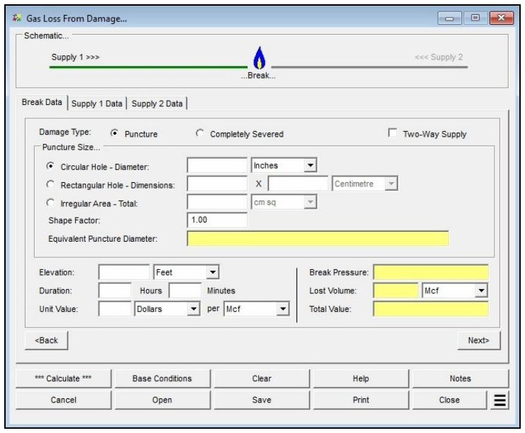
| Parameter | Description |
|---|---|
| Damage Type | Specifies whether the damage is a puncture (a hole in the side wall of the pipe) or a completely severed pipe (cut in two). |
| Two-Way Supply | When selected, indicates there are two sources of supply to the break, enabling the Supply 2 Data tab. |
| Puncture Size | Specifies the puncture geometry: Circular Hole (average diameter), Rectangular Hole (width and length), or Irregular Area (total area of the opening). |
| Shape Factor | Specifies the flow “efficiency” for the puncture, used to increase or decrease the computed flow through the opening. Reduce it for punctures that are not clean, or for irregular or rectangular shapes. |
| Elevation | Specifies the height above mean sea level at the break. Only displayed when the Atmospheric Pressure Method in the Base Conditions is not set to “None” or “None – Entered Value.” |
| Atm Pressure | Specifies the atmospheric pressure at the break. Only displayed when the Atmospheric Pressure Method in the Base Conditions is set to “None – Entered Value.” |
| Duration | Specifies the time elapsed between when the damage occurred and when the flow through the damage was turned off. |
| Unit Value | Specifies the cost of the lost gas per unit of volume or energy. |
| Lost Volume Units | Selects the dimensional units in which the lost volume is reported (e.g., Mcf). |
| Components (Supply 1 / Supply 2) | Lists the pipes and fittings associated with the supply route. Each route must contain at least one component. Limit the list to the portions most directly supplying the break — typically back to a pipe at least twice the size of the damaged pipe, or to a regulator or supply point. |
| Efficiency (Supply 1) | Specifies the hydraulic efficiency value for the supply piping and fittings. |
| Equation (Supply 1) | Specifies the pipe flow equation used to calculate values along the supply piping. |
| Pressure (Supply 1 / Supply 2) | Specifies the pressure at the inlet (upstream) end of the supply piping. Should represent a stable supply pressure, accounting for the lower pressure that occurs because of flow from the break. |
| Temperature (Supply 1 / Supply 2) | Specifies the flowing temperature of the gas. |
| Flow Limit (Supply 1 / Supply 2) | When selected, the user-entered flow rate limit is used as the maximum permissible flow for the supply route — useful when a regulator, meter capacity, or other constraint limits the source. |
| Base Pressure / Base Temperature | Set on the Base Conditions screen. Establishes the base (reference) pressure and temperature used to report standard-volume values. |
| Use Gas Properties File | Set on the Base Conditions screen. Selects a gas properties file for the composition, or “None” to enter the gas property values manually. |
| Atmospheric Pressure Method | Set on the Base Conditions screen. Determines how atmospheric pressure is established and controls whether the Elevation or Atm Pressure fields are displayed. |
Part 2: Outputs/Reports
- If you need to modify an input parameter, click the CALCULATE button again after the change.
- Review the calculated values: Equivalent Puncture Diameter, Break Pressure, Lost Volume, and Total Value, along with the Flow Rate for each supply route.
- To SAVE the calculation, click the Save command button (calculation files use the .los extension).
- To print the data values and results, click the Print command button and configure the Print Settings screen.
- To compare results by changing a value without re-entering all data, use the Open Duplicate Calculation Additional Action.
Results
| Output | Description |
|---|---|
| Equivalent Puncture Diameter | Displays the calculated puncture size expressed as the equivalent diameter of a circular hole. |
| Break Pressure | Displays the estimated pressure at the break. For a completely severed, two-way supply, it is computed as the average of the outlet pressures of the two supply routes — usually atmospheric (0 gauge), unless flow in one or both pipes is choked. |
| Lost Volume | Displays the amount of gas lost through the break over the specified duration, reported as a standard volume adjusted to the base pressure and temperature. |
| Total Value | Displays the total monetary value of the estimated lost gas, based on the Unit Value. |
| Flow Rate (Supply 1) | Displays the calculated flow rate through the Supply 1 route. |
| Pipe Flow (Supply 2) | Displays the calculated flow rate through the Supply 2 route. Only relevant when Two-Way Supply is selected. |
| Outlet Pressure (Supply 1 / Supply 2) | Displays the calculated pressure at the downstream (break) end of the supply piping for the route. Only displayed when the Completely Severed option is selected. |
Note: Pressure values are entered and displayed in gauge units, while flow rate and volume values represent standard volumes adjusted to the base pressure and temperature. Flow along a supply route cannot exceed the rate that would produce sonic velocity; in severe-damage cases the flow may be limited to sonic speeds, and the downstream pressure may then exceed atmospheric. The number of decimal places shown for any calculated item can be set under File > Preferences > Decimals.
References
- American Gas Association, Report No. 3, Orifice Metering Of Natural Gas, Third Edition, 1992.
FAQ
-
When should I treat the damage as severed instead of a puncture?When the damage is large relative to the pipe. As a rule of thumb, if the puncture is more than about 75% of the pipe diameter (its area exceeds roughly 75% of the pipe’s flow area), the puncture assumption is no longer valid and the damage should be treated as completely severed.
-
What is the shape factor and when should I change it?
The shape factor adjusts the flow through the puncture to account for the fact that a real opening is not a clean, sharp-edged circular orifice. It should generally be reduced for punctures that are not clean, or for irregular or rectangular openings, to decrease the computed flow accordingly.
-
How do I handle a break that can be fed from two directions?Select the Two-Way Supply option, which enables the Supply 2 Data tab, and enter the components and conditions for both the Supply 1 and Supply 2 routes. If the break is fed from only one direction, enter data on the Supply 1 Data tab only.