
Introduction
The Relief Valve Values calculator determines the key operating parameters for a relief valve — including flow rate, inlet pressure, outlet pressure, or required orifice area/valve factor — given the selected valve model and operating conditions. Seven industry and manufacturer-specific sizing equations are supported, covering the most common relief valve makes used in natural gas distribution and transmission stations. Unlike the Relief Valve & Piping System and Regulator & Relief Valve System routines, this calculator considers only the relief valve itself; the effect of associated upstream, intermediate, or downstream piping is not included.
Important: The Relief Valve Values calculation routine models a fully opened relief valve under nominal operating conditions. It does not model the sense line, control system, or the internal valve dynamics that determine whether the valve is open or closed. Build-up — the allowable increase in upstream pressure above set pressure before the valve reaches full capacity — is not automatically calculated; the user must manually adjust the inlet pressure to account for build-up if required. Use the Regulator & Relief Valve System or Relief Valve & Piping System routines when build-up, station piping pressure drop, or full system interaction is needed.
Background
A relief valve is an automatic pressure-control device that opens to vent gas downstream — usually to atmosphere through a vent stack — whenever the upstream pressure rises to or above the valve’s set pressure. The valve remains closed when upstream pressure is below the set pressure and opens fully once the set pressure is reached, allowing excess gas to escape and limiting the maximum system pressure.
Capacity and Valve Factor
The capacity of a relief valve is governed by two factors: the valve’s physical size (characterised by a valve factor) and the pressure differential across the valve opening. Because the downstream pressure is typically near atmospheric, increasing capacity generally requires allowing the upstream pressure to rise. The maximum achievable capacity for any valve size is reached at sonic (critical) flow — the condition where gas velocity through the valve opening equals the local speed of sound. As a rule of thumb, critical flow occurs when the absolute upstream pressure is approximately twice the absolute downstream pressure. Once sonic flow is established, further increases in upstream pressure do not increase the mass flow rate through the valve; only a larger valve can pass more gas.
The valve factor is defined differently by different manufacturers and even between models from the same manufacturer. It cannot be used to directly compare capacities between different makes or models. To compare two relief valves, calculate the flow rate of each under the same inlet and outlet conditions using the appropriate manufacturer equation, then compare the results.
Valve Factor Ratio
When a valve is selected from the Relief Valve Property Table, GASCalc reads its rated valve factor and uses it to compute the required valve factor — the factor needed to pass the specified flow at the given conditions. The Valve Factor Ratio is the ratio of the required factor to the rated factor, expressed as a percentage. A ratio of 100% means the valve is operating exactly at its rated capacity. A ratio below 100% means the valve has spare capacity; a ratio above 100% means the specified duty exceeds the valve’s rating and a larger valve should be selected.
Equations
Each sizing equation is specific to a manufacturer or standard and must be matched to the appropriate valve model. All equations evaluate two flow regimes: subsonic (non-critical) and sonic (critical). The transition criterion — the pressure ratio at which critical flow begins — differs between methods. A base-condition correction factor FB is common to all methods to adjust for base pressures and temperatures that differ from the standard reference conditions.
American Meter — AFV
Suitable for the American Meter Axial Flow Valve used as a relief valve. The sonic transition occurs when the differential pressure (P₁ − P₂) equals or exceeds the critical flow factor threshold Fk × Xt × P₁.
\text{Subsonic} - \text{If } (P_1 - P_2) < (F_k \times X_t \times P_1)\text{Subsonic} – \text{If } (P_1 – P_2) < (F_k \times X_t \times P_1)
Q = 1359.792 \times F_B \times C_V \times Y \times \sqrt{\frac{P_1^2 - P_1 P_2}{SG \times T_F}}Q = 1359.792 \times F_B \times C_V \times Y \times \sqrt{\frac{P_1^2 – P_1 P_2}{SG \times T_F}}
Y = 1 - \frac{P_1 - P_2}{3 \times F_k \times X_t \times P_1}Y = 1 – \frac{P_1 – P_2}{3 \times F_k \times X_t \times P_1}
\text{Sonic} - \text{If } (P_1 - P_2) \geq (F_k \times X_t \times P_1)\text{Sonic} – \text{If } (P_1 – P_2) \geq (F_k \times X_t \times P_1)
Q = 906.981 \times F_B \times C_V \times P_1 \times \sqrt{\frac{F_k \times X_t}{SG \times T_F}}Q = 906.981 \times F_B \times C_V \times P_1 \times \sqrt{\frac{F_k \times X_t}{SG \times T_F}}
F_B = \left(\frac{T_B}{520}\right) \times \left(\frac{14.73}{P_B}\right)F_B = \left(\frac{T_B}{520}\right) \times \left(\frac{14.73}{P_B}\right)
Where:
CV − Valve factor (cfh/psi)
Fk − Ratio of specific heat factor = k / 1.4 (dimensionless)
Xt − Critical flow factor (dimensionless)
Y − Expansion factor (dimensionless)
FB − Base condition correction factor (dimensionless)
PB − Base pressure (psia)
TB − Base temperature (Rankine)
Anderson-Greenwood
Suitable for Anderson Greenwood Model 90 and 9000 relief valves. The sonic transition is based on set pressure (Pset ≥ 15 psig).
\text{Subsonic} - \text{If } P_{set} < 15 \ \text{psig}\text{Subsonic} – \text{If } P_{set} < 15 \ \text{psig}
Q = 278700 \times F_B \times A \times F \times KD \times P_1 \times \sqrt{\frac{1}{SG \times T_F \times Z \times MW_{air}}}Q = 278700 \times F_B \times A \times F \times KD \times P_1 \times \sqrt{\frac{1}{SG \times T_F \times Z \times MW_{air}}}
\text{Sonic} - \text{If } P_{set} \geq 15 \ \text{psig}\text{Sonic} – \text{If } P_{set} \geq 15 \ \text{psig}
Q = 379.2 \times F_B \times A \times C \times K \times P_1 \times \sqrt{\frac{1}{SG \times T_F \times Z \times MW_{air}}}Q = 379.2 \times F_B \times A \times C \times K \times P_1 \times \sqrt{\frac{1}{SG \times T_F \times Z \times MW_{air}}}
F_B = \left(\frac{T_B}{520}\right) \times \left(\frac{14.7}{P_B}\right)F_B = \left(\frac{T_B}{520}\right) \times \left(\frac{14.7}{P_B}\right)
C = 520\sqrt{k \times \left[\frac{2}{k+1}\right]^{\frac{k+1}{k-1}}}C = 520\sqrt{k \times \left[\frac{2}{k+1}\right]^{\frac{k+1}{k-1}}}
F = \sqrt{\left(\frac{k}{k-1}\right) \times \left[R^{\frac{2}{k}} - R^{\frac{k+1}{k}}\right]}F = \sqrt{\left(\frac{k}{k-1}\right) \times \left[R^{\frac{2}{k}} – R^{\frac{k+1}{k}}\right]}
R = \frac{P_2}{P_1}R = \frac{P_2}{P_1}
KD = C_1 \times \frac{P_2^{X_2}}{P_1^{X_1}}KD = C_1 \times \frac{P_2^{X_2}}{P_1^{X_1}}
Where:
A − Orifice area (square inches)
C − Sonic flow coefficient (dimensionless)
C₁ − Discharge coefficient constant (dimensionless)
F − Subsonic flow coefficient (dimensionless)
FB − Base condition correction factor (dimensionless)
K − Sonic discharge coefficient (dimensionless)
KD − Discharge coefficient (dimensionless)
MWair − Molecular weight of air
PB − Base pressure (psia)
R − Pressure ratio P₂/P₁ (dimensionless)
TB − Base temperature (Rankine)
X₁, X₂ − Discharge coefficient pressure exponents (dimensionless)
Z − Compressibility factor (dimensionless)
API-520
Suitable for relief valves compliant with API Recommended Practice 520. The sonic transition criterion is based on the critical pressure ratio XPC = [2/(k+1)]^(k/(k−1)).
\text{Subsonic} - \text{If } P_2 > P_1 \times XPC\text{Subsonic} – \text{If } P_2 > P_1 \times XPC
Q = 51817.8 \times F_B \times A \times F_2 \times KD \times \sqrt{\frac{P_1^2 - P_1 P_2}{SG \times T_F \times Z}}Q = 51817.8 \times F_B \times A \times F_2 \times KD \times \sqrt{\frac{P_1^2 – P_1 P_2}{SG \times T_F \times Z}}
\text{Sonic} - \text{If } P_2 \leq P_1 \times XPC\text{Sonic} – \text{If } P_2 \leq P_1 \times XPC
Q = 70.5 \times F_B \times A \times C \times KD \times KB \times P_1 \times \sqrt{\frac{1}{SG \times T_F \times Z}}Q = 70.5 \times F_B \times A \times C \times KD \times KB \times P_1 \times \sqrt{\frac{1}{SG \times T_F \times Z}}
F_B = \left(\frac{T_B}{520}\right) \times \left(\frac{14.73}{P_B}\right)F_B = \left(\frac{T_B}{520}\right) \times \left(\frac{14.73}{P_B}\right)
C = 520\sqrt{k \times \left[\frac{2}{k+1}\right]^{\frac{k+1}{k-1}}}C = 520\sqrt{k \times \left[\frac{2}{k+1}\right]^{\frac{k+1}{k-1}}}
F_2 = \sqrt{\frac{k}{k-1} \cdot R^{\frac{2}{k}} \times \left[1 - \frac{R^{\frac{k-1}{k}}}{1 - R}\right]}F_2 = \sqrt{\frac{k}{k-1} \cdot R^{\frac{2}{k}} \times \left[1 – \frac{R^{\frac{k-1}{k}}}{1 – R}\right]}
R = \frac{P_2}{P_1}R = \frac{P_2}{P_1}
XPC = \left[\frac{2}{k+1}\right]^{\frac{k}{k-1}}XPC = \left[\frac{2}{k+1}\right]^{\frac{k}{k-1}}
Where:
A − Orifice area (square inches)
C − Sonic flow coefficient (dimensionless)
F₂ − Subsonic flow coefficient (dimensionless)
FB − Base condition correction factor (dimensionless)
KB − Capacity correction factor (dimensionless)
KD − Discharge coefficient = 0.975 (dimensionless)
PB − Base pressure (psia)
R − Pressure ratio P₂/P₁ (dimensionless)
TB − Base temperature (Rankine)
XPC − Critical pressure ratio (dimensionless)
Z − Compressibility factor (dimensionless)
ASME Boiler and Pressure Vessel Code (ASME-BPV)
Suitable for relief valves compliant with ASME BPV Code Section VIII. The sonic transition criterion is identical to API-520, based on the critical pressure ratio XPC = [2/(k+1)]^(k/(k−1)). The leading constants differ slightly from API-520 as derived from the ASME reference.
\text{Subsonic} - \text{If } P_2 > P_1 \times XPC\text{Subsonic} – \text{If } P_2 > P_1 \times XPC
Q = 51789 \times F_B \times A \times F_2 \times KD \times \sqrt{\frac{P_1^2 - P_1 P_2}{SG \times T_F \times Z}}Q = 51789 \times F_B \times A \times F_2 \times KD \times \sqrt{\frac{P_1^2 – P_1 P_2}{SG \times T_F \times Z}}
\text{Sonic} - \text{If } P_2 \leq P_1 \times XPC\text{Sonic} – \text{If } P_2 \leq P_1 \times XPC
Q = 70.44 \times F_B \times A \times C \times KD \times KB \times P_1 \times \sqrt{\frac{1}{SG \times T_F \times Z}}Q = 70.44 \times F_B \times A \times C \times KD \times KB \times P_1 \times \sqrt{\frac{1}{SG \times T_F \times Z}}
F_B = \left(\frac{T_B}{520}\right) \times \left(\frac{14.73}{P_B}\right)F_B = \left(\frac{T_B}{520}\right) \times \left(\frac{14.73}{P_B}\right)
C = 520\sqrt{k \times \left[\frac{2}{k+1}\right]^{\frac{k+1}{k-1}}}C = 520\sqrt{k \times \left[\frac{2}{k+1}\right]^{\frac{k+1}{k-1}}}
F_2 = \sqrt{\frac{k}{k-1} \cdot R^{\frac{2}{k}} \times \left[1 - \frac{R^{\frac{k-1}{k}}}{1 - R}\right]}F_2 = \sqrt{\frac{k}{k-1} \cdot R^{\frac{2}{k}} \times \left[1 – \frac{R^{\frac{k-1}{k}}}{1 – R}\right]}
R = \frac{P_2}{P_1}R = \frac{P_2}{P_1}
XPC = \left[\frac{2}{k+1}\right]^{\frac{k}{k-1}}XPC = \left[\frac{2}{k+1}\right]^{\frac{k}{k-1}}
Where:
A − Orifice area (square inches)
C − Sonic flow coefficient (dimensionless)
F₂ − Subsonic flow coefficient (dimensionless)
FB − Base condition correction factor (dimensionless)
KB − Capacity correction factor (dimensionless)
KD − Discharge coefficient = 0.975 (dimensionless)
PB − Base pressure (psia)
R − Pressure ratio P₂/P₁ (dimensionless)
TB − Base temperature (Rankine)
XPC − Critical pressure ratio (dimensionless)
Z − Compressibility factor (dimensionless)
Fisher Controls
Suitable for Fisher Controls relief valves, control valves, and regulators used as relief valves. The sonic transition criterion is a pressure ratio of P₂/P₁ ≤ 0.5.
\text{Subsonic} - \text{If } \frac{P_2}{P_1} > 0.5\text{Subsonic} – \text{If } \frac{P_2}{P_1} > 0.5
Q = F_B \times C_g \times P_1 \times \sqrt{\frac{520}{SG \times T_F}} \times \sin\!\left(\frac{59.638}{C_1}\sqrt{\frac{P_1 - P_2}{P_1}}\right)Q = F_B \times C_g \times P_1 \times \sqrt{\frac{520}{SG \times T_F}} \times \sin\!\left(\frac{59.638}{C_1}\sqrt{\frac{P_1 – P_2}{P_1}}\right)
\text{Sonic} - \text{If } \frac{P_2}{P_1} \leq 0.5\text{Sonic} – \text{If } \frac{P_2}{P_1} \leq 0.5
Q = F_B \times C_g \times P_1 \times \sqrt{\frac{520}{SG \times T_F}}Q = F_B \times C_g \times P_1 \times \sqrt{\frac{520}{SG \times T_F}}
F_B = \left(\frac{T_B}{520}\right) \times \left(\frac{14.7}{P_B}\right)F_B = \left(\frac{T_B}{520}\right) \times \left(\frac{14.7}{P_B}\right)
Where:
Cg − Gas valve sizing coefficient
C₁ − Valve recovery coefficient, assumed constant for a specific size and model
FB − Base condition correction factor (dimensionless)
PB − Base pressure (psia)
TB − Base temperature (Rankine)
Note: The argument of the sine function is in degrees.
Flow Safe
Suitable for Flow Safe F70PR series pilot-operated pressure relief valves. The sonic transition criterion uses the critical pressure ratio XPC = [2/(k+1)]^(k/(k−1)).
\text{Subsonic} - \text{If } P_2 > P_1 \times XPC\text{Subsonic} – \text{If } P_2 > P_1 \times XPC
Q = 278700 \times F_B \times A \times F_2 \times KD \times KC \times \sqrt{\frac{P_1^2 - P_1 P_2}{SG \times T_F \times Z \times MW_{AIR}}}Q = 278700 \times F_B \times A \times F_2 \times KD \times KC \times \sqrt{\frac{P_1^2 – P_1 P_2}{SG \times T_F \times Z \times MW_{AIR}}}
\text{Sonic} - \text{If } P_2 \leq P_1 \times XPC\text{Sonic} – \text{If } P_2 \leq P_1 \times XPC
Q = 379.2 \times F_B \times A \times C \times KD \times KC \times P_1 \times \sqrt{\frac{1}{SG \times T_F \times Z \times MW_{AIR}}}Q = 379.2 \times F_B \times A \times C \times KD \times KC \times P_1 \times \sqrt{\frac{1}{SG \times T_F \times Z \times MW_{AIR}}}
F_B = \left(\frac{T_B}{520}\right) \times \left(\frac{14.7}{P_B}\right)F_B = \left(\frac{T_B}{520}\right) \times \left(\frac{14.7}{P_B}\right)
C = 520\sqrt{k \times \left[\frac{2}{k+1}\right]^{\frac{k+1}{k-1}}}C = 520\sqrt{k \times \left[\frac{2}{k+1}\right]^{\frac{k+1}{k-1}}}
F_2 = \sqrt{\frac{k}{k-1} \cdot R^{\frac{2}{k}} \times \left[\frac{1 - R^{\frac{k-1}{k}}}{1 - R}\right]}F_2 = \sqrt{\frac{k}{k-1} \cdot R^{\frac{2}{k}} \times \left[\frac{1 – R^{\frac{k-1}{k}}}{1 – R}\right]}
R = \frac{P_2}{P_1}R = \frac{P_2}{P_1}
XPC = \left[\frac{2}{k+1}\right]^{\frac{k}{k-1}}XPC = \left[\frac{2}{k+1}\right]^{\frac{k}{k-1}}
Where:
A − Orifice area (square inches)
C − Sonic flow coefficient (dimensionless)
F₂ − Subsonic flow coefficient (dimensionless)
FB − Base condition correction factor (dimensionless)
KC − Rupture disk correction factor (dimensionless)
KD − Discharge coefficient based on set pressure (see cited reference)
MWAIR − Molecular weight of air
PB − Base pressure (psia)
R − Pressure ratio P₂/P₁ (dimensionless)
TB − Base temperature (Rankine)
XPC − Critical pressure ratio (dimensionless)
Z − Compressibility factor (dimensionless)
Mooney Controls
Suitable for Mooney Controls regulators used as relief valves. The sonic transition criterion is (P₁ − P₂)/P₂ ≥ 0.64.
\text{Subsonic} - \text{If } \frac{P_1 - P_2}{P_2} < 0.64\text{Subsonic} – \text{If } \frac{P_1 – P_2}{P_2} < 0.64
Q = F_B \times C_g \times P_1 \times \sqrt{\frac{520}{SG \times T_F}} \times \sin\!\left(\frac{59.638}{C_1}\sqrt{\frac{P_1 - P_2}{P_1}}\right)Q = F_B \times C_g \times P_1 \times \sqrt{\frac{520}{SG \times T_F}} \times \sin\!\left(\frac{59.638}{C_1}\sqrt{\frac{P_1 – P_2}{P_1}}\right)
\text{Sonic} - \text{If } \frac{P_1 - P_2}{P_2} \geq 0.64\text{Sonic} – \text{If } \frac{P_1 – P_2}{P_2} \geq 0.64
Q = F_B \times C_g \times P_1 \times \sqrt{\frac{520}{SG \times T_F}}Q = F_B \times C_g \times P_1 \times \sqrt{\frac{520}{SG \times T_F}}
F_B = \left(\frac{T_B}{520}\right) \times \left(\frac{14.7}{P_B}\right)F_B = \left(\frac{T_B}{520}\right) \times \left(\frac{14.7}{P_B}\right)
Where:
Cg − Gas valve sizing coefficient
C₁ − Valve recovery coefficient, assumed constant for a specific size and model
FB − Base condition correction factor (dimensionless)
PB − Base pressure (psia)
TB − Base temperature (Rankine)
Note: The argument of the sine function is in degrees.
Rockwell & Equimeter
Suitable for Equimeter, Sensus, and Rockwell relief valves. The sonic transition is at an upstream-to-downstream absolute pressure ratio P₁/P₂ ≥ 1.894.
\text{Subsonic} - \text{If } \frac{P_1}{P_2} < 1.894\text{Subsonic} – \text{If } \frac{P_1}{P_2} < 1.894
Q = F_B \times K \times \sqrt{\frac{0.6 \, P_2 \,(P_1 - P_2)}{SG}}Q = F_B \times K \times \sqrt{\frac{0.6 \, P_2 \,(P_1 – P_2)}{SG}}
\text{Sonic} - \text{If } \frac{P_1}{P_2} \geq 1.894\text{Sonic} – \text{If } \frac{P_1}{P_2} \geq 1.894
Q = \frac{F_B \times K \times P_1}{2} \times \sqrt{\frac{0.6}{SG}}Q = \frac{F_B \times K \times P_1}{2} \times \sqrt{\frac{0.6}{SG}}
F_B = \left(\frac{T_B}{520}\right) \times \left(\frac{14.65}{P_B}\right)F_B = \left(\frac{T_B}{520}\right) \times \left(\frac{14.65}{P_B}\right)
Where:
FB − Base condition correction factor (dimensionless)
K − Regulator valve constant
PB − Base pressure (psia)
TB − Base temperature (Rankine)
Note: This method uses a reference base pressure of 14.65 psia in the FB correction factor, rather than the 14.73 psia used by most other methods.
Common Equation Variables
The following definitions apply across all methods:
k − Specific heat ratio (dimensionless)
P1 − Inlet (upstream) absolute pressure (psia); P₁ = P₁_gauge + PATM
P2 − Outlet (downstream) absolute pressure (psia); P₂ = P₂_gauge + PATM
PATM − Atmospheric pressure at the valve location (psia)
Q − Volumetric flow rate at the specified base pressure and temperature (cfh)
SG − Specific gravity (dimensionless)
TF − Inlet gas flowing temperature (Rankine)
Case Guide
Part 1: Create Case
- Select the Relief Valve Values application from the Valves and Fittings Module.
- From the Valves & Fittings menu, select the Relief Valve Values item. The Relief Valve Values calculation screen will be displayed.
- Click the Clear button to set all values to blank (null).
- Click the Base Conditions button. Enter the base pressure and temperature, select or enter gas property values, choose the Atmospheric Pressure Method, and optionally select a Compressibility Factor Method. Click Apply to save and return.
- In the Relief Valve Data section, click the ? button next to Size/Type to open the Device Selection screen. Select the appropriate manufacturer, model, body size, and orifice size. Click Apply — the Rated Valve Factor will be populated automatically from the Relief Valve Property Table.
- If needed, the Required Valve Factor can be overwritten with a user-specified value; this overridden value will be used in place of the rated factor during the calculation.
- Click the red label of the item to be calculated — Flow Rate, Inlet Pressure, Outlet Pressure, Required Valve Factor, or Required Area — until it is underlined.
- In the Operating Data section, enter the known values: Inlet Pressure, Outlet Pressure, Inlet Temperature, Elevation, and, if required by the selected equation, Set Pressure. Select appropriate dimensional units for each field.
- Click the Calculate button to compute results.
Input Parameters
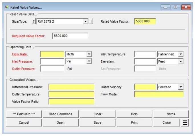
| Parameter | Description |
|---|---|
| Size/Type | Specifies the relief valve Size/Type Code. Click the ? command button to select a device using the Device Selection screen. Selecting a device automatically loads the associated Rated Valve Factor from the Relief Valve Property Table. |
| Rated Valve Factor | The rated (published) valve sizing factor for the selected relief valve, loaded automatically when a Size/Type is selected. Displayed in yellow. |
| Required Valve Factor | The valve factor required to pass the specified flow at the given conditions. Automatically populated when a Size/Type is selected; may be overwritten by the user. Click the red label to select this as the unknown to be solved. |
| Flow Rate | Specifies or displays the flow rate through the relief valve. Click the red label to select this as the unknown to be solved. |
| Inlet Pressure | Specifies or displays the gauge pressure on the inlet (upstream) side of the valve. Click the red label to select this as the unknown to be solved. |
| Outlet Pressure | Specifies or displays the gauge pressure on the outlet (downstream) side of the valve. Depending on the Set Point Droop value, it may or may not match the Set Pressure. Click the red label to select this as the unknown to be solved. |
| Set Pressure | Specifies the set pressure for the relief valve. Required by the Anderson-Greenwood equation to determine the flow regime. |
| Inlet Temperature | Specifies the flowing temperature of the gas at the inlet (upstream) side of the valve. |
| Elevation | Specifies the height above mean sea level at the relief valve location. Displayed when the Atmospheric Pressure Method in Base Conditions is not set to “None” or “None – Entered Value.” |
| Atm Pressure | Specifies the atmospheric pressure at the relief valve location. Displayed only when the Atmospheric Pressure Method in Base Conditions is set to “None – Entered Value.” |
Part 2: Outputs/Reports
- If you need to modify an input parameter, update the value and click the CALCULATE button again.
- To SAVE, click the Save command button. Provide a file name and location (.rlf file).
- To open a previously saved calculation, click the Open command button and select the .rlf file.
- To generate a REPORT, click the Print command button to access the Print Settings screen.
- To calculate results across a range of inlet pressures or flow rates, use Additional Actions > Calculate Table of Results.
- To compare results for different valve models or equations, use Additional Actions > Open Duplicate Calculation.
- To add a title or notes to the calculation, click the Notes command button.
Results
| Output | Description |
|---|---|
| Rated Valve Factor | The rated (published) valve sizing factor for the selected relief valve, read from the Relief Valve Property Table. |
| Required Valve Factor | The valve factor required to pass the specified flow at the given conditions. Compared against the Rated Valve Factor to determine adequacy. |
| Rated Area | The published orifice area for the selected valve (square inches). |
| Flow Rate | The volumetric flow through the fully opened valve at base conditions. Displayed when selected as the unknown to be solved (cfh or Mcfh). |
| Inlet Pressure | The inlet (upstream) gauge pressure. Displayed when selected as the unknown to be solved (psig or millibar). |
| Outlet Pressure | The outlet (downstream) gauge pressure. Displayed when selected as the unknown to be solved (psig or millibar). |
| Differential Pressure | The calculated linear pressure difference across the valve (psi or millibar). Displayed in red if below the minimum value listed in the Relief Valve Property Table. |
| Outlet Velocity | The calculated gas velocity at the valve outlet, computed from the flow rate, outlet temperature, outlet pressure, and listed outlet diameter (ft/sec or m/sec). |
| Outlet Temperature | The estimated gas temperature at the valve outlet, calculated using the Joule-Thomson method (°F or °C). |
| Flow Mode | Reports whether the valve is operating in Subsonic or Sonic (Critical Flow) regime. |
| Valve Factor Ratio | The ratio of the Required Valve Factor to the Rated Valve Factor (%). Values above 100% indicate the valve is undersized for the specified duty. |
| Area Ratio | The ratio of the Required Area to the Rated Area (%). Available when area-based equations (API-520, ASME-BPV, Flow Safe, Anderson-Greenwood) are used. |
References
- American Meter Company — Axial Flow Valves Capacity Tables, TDB 9610.5.
- American Petroleum Institute — Recommended Practice 520, Sizing, Selection, and Installation of Pressure-Relieving Devices in Refineries, Sixth Edition, March 1993.
- American Society of Mechanical Engineering — Boiler and Pressure Vessel Code, Section VIII, Pressure Vessels.
- Equimeter Inc. — Bulletin Model 441-57S, R-1360 Rev 4.
- Rockwell International — Bulletin Model 441-57S, R-1360 Rev 3.
- Fisher Controls — Catalog 10, Sizing and Selection Data.
- Mooney Controls — Sizing, Compressible Gases.
- Anderson Greenwood — Catalog 90/9000-US.96, 1996.
- Flow Safe — F70PR Series Pilot-Operated Pressure Relief Valves, Catalog F70PR0499REVA0808, March 1999.
FAQ
-
What type of station does the Regulator & Monitor System calculator model?
The calculator models a two-stage (monitor-style) regulator and relief valve station in which gas pressure is reduced sequentially across two independent regulator stages. Each stage has its own relief valve and vent stack. This configuration is commonly used when codes require automatic overpressure protection at both stages of pressure reduction.
-
Which regulatory codes does this calculator support for compliance checks?
The calculator supports two regulatory codes for compliance checks: US DOT 49 CFR Part 192 (2019 edition) and ASME B31.8 (2007 edition). When a code is selected, the calculator compares the maximum calculated pressure in each piping section against the user-specified MAOP for that section using the allowable limits defined by that code. Results that exceed the allowable limits are highlighted in red on the Compliance data tab.
You can also select “None” to perform the hydraulic and flow calculations without any code-based compliance checking.
-
What information do I need before running this calculator?
Before running the calculator, you will need the following for each stage of the station:
For the supply piping, you need the minimum and maximum inlet pressures, the flowing gas temperature, the pipe and fitting specifications (size, wall thickness, length), and the pipe flow equation and efficiency. For each regulator, you need to select the manufacturer and model from the device database and enter the set pressure. For each relief valve, you need to select the model, enter the set pressure, minimum build-up pressure, and number of installed valves. For the vent stacks, you need the pipe and fitting specifications and whether the outlet discharges to atmosphere.
You will also need the gas composition or a gas properties file, base conditions (pressure and temperature), the minimum and maximum outlet flow rates, and — if performing compliance checks — the MAOP for each of the five piping sections: Upstream (Supply 1), Intermediate 1, Upstream (Supply 2), Intermediate 2, and Outlet.
-
What operating modes does the calculator support, and when should I use each one?
The calculator supports six operating modes, each representing a different assumption about which regulators are operating normally and which have failed.
Use Failed Upstream or Failed Downstream when you want to evaluate a single regulator failure while the other stage operates normally — these are the most common code-required failure scenarios. Use Failed Single to evaluate each regulator failing independently in two separate analyses. Use Failed Double to evaluate simultaneous failure of both regulators, which is the most conservative failure case. Use Normal to verify pressures and velocities under steady-state operation, and Normal Maximum to calculate the maximum flow capacity the combined station can deliver.
-
How does the calculator determine the inlet pressure to the second-stage supply piping?
The inlet pressure to the second-stage supply piping is not a direct user input — it is calculated internally based on the selected operating mode.
In most failure modes (Failed Single, Failed Double, Failed Downstream, Normal, and Normal Maximum), the second-stage inlet pressure is set equal to the first-stage regulator set pressure minus the pressure drop across the first-stage intermediate piping. In the Failed Upstream mode, however, the second-stage inlet pressure is instead set to the calculated build-up pressure at the outlet of the first-stage intermediate piping. This build-up pressure may be higher than the set pressure, since the first-stage relief valve is actively venting and the intermediate piping is operating under overpressure conditions. This distinction is important for correctly sizing the second-stage components in a failed upstream scenario.
-
What does the Relief Branch – First fitting do, and when should I use it?
In most physical installations, the relief valve is not installed inline with the intermediate piping — it is connected via a branch tee. This means the piping upstream of the tee carries both the relief valve flow and any downstream system flow, while the branch piping leading to the relief valve carries only the relief valve flow.
The Relief Branch – First component is a special fitting you add to the intermediate piping component list to tell the calculator where this branch point occurs. The calculator automatically splits the flow at that point: combined flow upstream of the component, relief-valve-only flow downstream. A Relief Branch – Second component is also available for installations with multiple identical relief valves sharing a common header, and is used to mark the point where the header splits to each individual valve.
-
What does the Operating Status field on the Relief Valve data tab mean?
The Operating Status field shows how the relief valve is responding under the calculated conditions. A status of Popping means the inlet pressure has reached or exceeded the relief valve set pressure and the valve is actively venting gas through the vent stack. A status of Continuously Closed means the inlet pressure is below the set pressure and the valve remains shut — no flow passes through the stack piping under those conditions.
In a failure scenario, you want to see Popping on the stage whose regulator has failed, which confirms the relief valve has opened and is handling the failed-regulator flow. If the relief valve is Continuously Closed when it should be venting, the relief valve may be undersized or the set pressure may be too high relative to the build-up pressure.
-
Is the 75% SMYS limit from DOT 192 §192.201(a)(2)(i) checked automatically?
No. When using the US DOT Part 192 regulatory code, the calculator performs MAOP-based compliance checks for each piping section, but it does not automatically evaluate the 75% SMYS hoop stress limit associated with §192.201(a)(2)(i).
If your calculated failed pressures are approaching the MAOP of any section — particularly on higher-pressure upstream piping — you should independently verify the resulting hoop stress using the Hoop Stress calculation routine in the Design & Stress Analysis module to confirm compliance with that limit.