
Introduction
This application calculates the various values associated with sizing and designing a gas service line, accounting for every component along the route — the tap or connection at the main, the excess flow valve (EFV), any attached fittings or pipe segments, the service pipe itself, and the riser/termination. It reports the equivalent length, pressure drop, maximum velocity, demand pressure, and a set of EFV-specific values, and it can solve for an unknown diameter, velocity, pressure, or load.
Only one red label and one blue label may be designated as the “unknown” to be solved for. All remaining items must be known. Pressure values shown or entered on this screen are gauge pressures, and flow values are expressed in “standard” volume units adjusted to the base pressure and temperature set on the Base Conditions screen.
Background
Sizing service lines has often been ignored, trivialized, or based on imprecise rule-of-thumb criteria. With the increased use of excess flow valves (EFVs), accurate sizing of service lines has become more important. Proper sizing ensures reliable, adequate service to the end user and correct operation of the EFV.
To properly size a service line, consideration must be given to all portions of the line — from the tap to the service termination, including any fittings or valves installed along the route. Each component contributes to the total pressure drop, so the pressure drop associated with each component needs to be analyzed. This can be done by performing an actual pressure drop calculation for each component or, more commonly, by including each component in a comprehensive calculation using an equivalent length value.
Equivalent Length
Equivalent length is a value that represents the equivalent hydraulic length of a component in terms of a specified inside diameter or pipe size. When used in a pipe flow equation, the equivalent length yields a pressure drop equal to that caused by the component under similar flow conditions. For example, if the pressure drop across a 2-inch valve is 0.4 psig, the equivalent length of the component equals the length of 2-inch pipe required to produce a 0.4 psig pressure drop under similar flow conditions.
When sizing main lines, the influence of fittings is often ignored because their equivalent length is small compared with the overall length. With service lines, however, the added equivalent length of installed fittings may be substantial — in many cases exceeding the physical service line length. Items such as pipe taps and EFVs tend to have fairly large pressure drops and associated equivalent lengths, so excluding them from the sizing calculation can considerably underestimate both the pressure drop across the service and its capacity.
Velocity Considerations
Some design criteria and standards establish a specific limit on the velocity of gas flow through a pipe. Because service lines often have small diameters, it is not uncommon to reach relatively high velocities compared with main line applications. When velocity is a required design criterion, the estimated maximum velocity can be calculated and controlled by varying the pipe size — increasing the pipe size decreases the velocity for similar flow conditions.
Calculation Method
As implemented, the Service Line Sizing routine combines many of its individual calculation routines into a single routine, allowing entry of a full range of components from the tapping tee at the main to the service termination at the inlet to the service regulator. The user can include as much or as little of this detail as is appropriate. Except for the EFV calculations, the equations for the various component pressure drops are documented in their specific calculation routines — this routine is a “method” of calculation rather than a single equation. The general method computes a pressure drop for each item in the following order, with the inlet pressure of each item equal to the outlet pressure of the previous one:
- Pipe Tap
- Excess Flow Valve
- Attached Components
- Service Line (Pipe) Segment
- Termination
Each pressure drop is calculated using the specified pipe flow equation, the specified pipe efficiency value, and the other specified flow and operating conditions. The inlet pressure to the pipe tap equals the specified supply (main) pressure.
Tap/Connection and Termination Pressure Drop
The pressure drop across the pipe tap is calculated from the assigned equivalent length for the selected tap or connection, extracted from the Fitting Property Table and adjusted to the specified service line size; if no tap is specified, this drop is assumed to be zero. The termination pressure drop is calculated the same way from the equivalent length of the fitting selected in the Riser/Termination Type list.
Excess Flow Valve Pressure Drop
The pressure drop across the EFV is calculated from its assigned equivalent length, extracted from the EFV Property Table and adjusted to the specified service line size; if no EFV is specified, this drop is assumed to be zero. The inlet pressure to the EFV equals the outlet pressure of the tap or connection.
Component and Service Line Pressure Drop
The pressure drop across the attached components is calculated using the specified inside diameter and length for pipes and the equivalent diameter and equivalent length for fittings, each adjusted to the specified service line size; all components are assumed attached directly to the upstream end of the service pipe segment. The pressure drop across the service pipe portion is then calculated from the associated or specified inside diameter, the specified pipe length, the pipe flow equation, the pipe efficiency, and the other flow and operating conditions. When a pipe Size/Type Code is assigned to the Diameter field, the inside diameter is read from the Pipe Property Table.
Minimum Severed Flow
The minimum severed flow rate is calculated by assuming the termination end of the service line is completely severed, unobstructed, and open to the atmosphere. The maximum flow that can pass through the service line and components under these conditions is calculated, limited to choked (sonic) flow. This value represents the lowest flow that would occur if the line were completely severed.
EFV-Specific Values
When an EFV is included in the service line, several associated values are calculated and displayed. Except for the estimated reset time, the Maximum By-Pass Rate, Maximum EFV Trip Point, and Minimum EFV Trip Point are extracted from the EFV Property Table (compiled from various manufacturers’ literature) and adjusted for the specified dimensional units. The Maximum Protected Length is calculated by determining the maximum service length that can flow at a rate at least as large as the Maximum EFV Trip Point for the specified EFV. An EFV does not activate at a single specific flow rate; the Minimum and Maximum EFV Trip Points represent the lower and upper bounds of the activation range.
EFV Reset Time
The EFV reset time — the estimated time required for the valve to reset after activation, once the downstream facilities are restored to a gas-tight condition — is calculated using the following equation:
RT = Q_{MAX} \times \sum V_{PT}RT = Q_{MAX} \times \sum V_{PT}
Where:
RT − Reset Time, seconds
QMAX − Maximum Reset Flow Rate, cfh
Case Guide
Part 1: Create Case
- From the Pipe menu, select the Service Line Sizing application (Regulators & Meters Module). The Service Line Sizing calculation screen will be displayed.
- Click the Clear command button to set all values to an empty (null) value.
- Click the Base Conditions command button, enter an appropriate base pressure and temperature, select a Gas Properties File (or “None” and enter the gas property values), select an Atmospheric Pressure Method and a Compressibility Factor Method, then click Apply.
- Click on the red label of the item to be calculated (the “unknown”) until it is underlined, and click on the blue label of the item to be calculated until it is underlined — or leave neither underlined if both items are known.
- Select the desired dimensional units for all data items.
- Set the Supply Conditions (Tap/Connection Type, Pressure, Elevation, Temperature) and the Excess Flow Valve Type.
- Set the Service Line values (Diameter, Length, Maximum Velocity, Pipe Efficiency, Pipe Flow Equation) and add any Fittings/Components to the list.
- Set the Demand Conditions (Load, Pressure) and the Riser/Termination Type.
- Click the CALCULATE command button to overview results.
Input Parameters
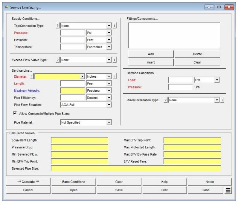
| Parameter | Description |
|---|---|
| Tap/Connection Type | Specifies the service line to the main tap or connection type. Click the ? command button to select a device using the Fitting Selection screen. |
| (Supply) Pressure | Specifies or displays the operating pressure of the main to which the service is connected. May be designated the “unknown” to be calculated. |
| Elevation | Specifies the average height above mean sea level of the service line and components. Only displayed when the Atmospheric Pressure Method in the Base Conditions is not set to “None” or “None – Entered Value”. |
| Atmospheric Pressure | Specifies the average atmospheric pressure of the service line and components. Only displayed when the Atmospheric Pressure Method in the Base Conditions is set to “None – Entered Value”. |
| Temperature | Specifies the gas flowing temperature value. |
| Excess Flow Valve Type | Specifies the type of excess flow valve. Click the ? command button to select a device using the EFV Selection screen. |
| Diameter | Specifies or displays the inside diameter of the service line. Click the ? command button to select a size using the Pipe Selection screen. May be designated the “unknown” to be calculated. |
| Length | Specifies or displays the hydraulic length of the service line. |
| Maximum Velocity | Specifies or displays the maximum velocity of the service line. When entered and the Diameter is calculated, it is used as a design parameter so the velocity does not exceed the specified value; otherwise it may be the “unknown” to be calculated. |
| Pipe Efficiency | Specifies the flow efficiency value of the service line. |
| Pipe Flow Equation | Specifies the flow equation to use during the calculation (e.g., AGA-Full, IGT-Improved). |
| Allow Composite/Multiple Pipe Sizes | When selected, multiple pipe sizes are allowed when selecting matching pipe Size/Type Codes. Only displayed and enabled when the Diameter value is “unknown”. |
| Pipe Material | Specifies the pipe material to use when selecting pipe sizes for calculating the Diameter value. Only displayed and enabled when the Diameter value is “unknown”. |
| Fittings/Components | Lists the pipe and fittings associated with the service line. Use the Add, Insert, Delete, and Clear command buttons below the list to modify its contents. |
| Load | Specifies or displays the gas demand on the service. May be designated the “unknown” to be calculated. |
| (Demand) Pressure | Specifies or displays the operating pressure at the terminating end of the pipe segment. May be designated the “unknown” to be calculated. |
| Riser/Termination Type | Specifies the type of fitting used at the terminating end of the service line. Click the ? command button to select a device using the Fitting Selection screen. |
| Base Pressure / Base Temperature | Set on the Base Conditions screen. Establishes the base (reference) pressure and temperature used to express standard volume flow values. |
| Atmospheric Pressure Method | Set on the Base Conditions screen. Determines how atmospheric pressure is established and controls whether the Elevation or Atmospheric Pressure fields are displayed. |
| Compressibility Factor Method | Set on the Base Conditions screen. Selects the compressibility factor method (or “None”); if other than “None”, an appropriate Gas Properties File must be selected. |
Part 2: Outputs/Reports
- If you need to modify an input parameter, click the CALCULATE button again after the change.
- Review the Calculated Values section, including Equivalent Length, Pressure Drop, Minimum Severed Flow, the EFV Trip Points, Maximum Protected Length, and EFV Reset Time. When the Diameter is calculated, the Selected Pipe Size is also displayed.
- To save the calculation, click the Save command button (calculation files use the .srv extension).
- To print the data values and results, click the Print command button and configure the Print Settings screen.
- To compare results by changing a value without re-entering all data, use the Open Duplicate Calculation Additional Action.
- To add a title or notes to the current calculation, click the Notes command button.
Results
| Output | Description |
|---|---|
| Equivalent Length | Displays the total equivalent length for all fittings and components associated with the service line, including the tap, EFV, and termination. When the Diameter is calculated, this value is based on the diameter of the largest selected pipe size. |
| Pressure Drop | Displays the calculated linear pressure drop for the entire service, from the tap to the termination. |
| Minimum Severed Flow | Displays the flow rate that would occur if the line were completely severed at the termination end (limited to choked/sonic flow). When the Diameter is calculated, this value is based on the diameter of the smallest selected pipe size. |
| Minimum EFV Trip Point | Displays the calculated lower range of flow through the specified EFV that will cause the valve to activate. Should be larger than the Load value, or the EFV might activate under full demand. |
| Maximum EFV Trip Point | Displays the calculated upper range of flow through the specified EFV that will cause the valve to activate. Should be less than the Minimum Severed Flow, or the valve may not trip if the line is severed near the termination. |
| Maximum Protected Length | Displays the calculated maximum length of service line that the specified EFV can effectively protect. When the Diameter is calculated, this value is based on the diameter of the smallest selected pipe size. |
| Maximum EFV By-Pass Rate | Displays the calculated maximum by-pass flow rate through the specified EFV after it has been activated. |
| EFV Reset Time | Displays the estimated time required for the specified EFV to reset after activation, once the downstream facilities are restored to a gas-tight condition. When the Diameter is calculated, it is based on the accumulated volume of the service pipe segment and the attached components. |
| Selected Pipe Size | Displays the selected pipe size(s) and their associated pipe lengths. Only displayed when the Diameter value is calculated. |
| (Demand) Pressure / (Supply) Pressure | Displays the operating pressure solved for at the corresponding end of the line when that pressure is designated the “unknown”. |
| Maximum Velocity | Displays the maximum velocity of the service line when it is designated the “unknown” rather than entered as a design parameter. |
Note: When sizing a service line, it is good practice to use the lowest anticipated operating pressure of the main as the Supply Pressure and the total connected load as the Load value. The number of decimal places shown for any calculated item can be set under File > Preferences > Decimals.
References
- EFV-specific values are derived from manufacturers’ literature as compiled in the GASCalc EFV Property Table; the reset time equation is derived (no external standard cited).
FAQ
-
What type of station does the Regulator & Monitor System calculator model?
The calculator models a two-stage (monitor-style) regulator and relief valve station in which gas pressure is reduced sequentially across two independent regulator stages. Each stage has its own relief valve and vent stack. This configuration is commonly used when codes require automatic overpressure protection at both stages of pressure reduction.
-
Which regulatory codes does this calculator support for compliance checks?
The calculator supports two regulatory codes for compliance checks: US DOT 49 CFR Part 192 (2019 edition) and ASME B31.8 (2007 edition). When a code is selected, the calculator compares the maximum calculated pressure in each piping section against the user-specified MAOP for that section using the allowable limits defined by that code. Results that exceed the allowable limits are highlighted in red on the Compliance data tab.
You can also select “None” to perform the hydraulic and flow calculations without any code-based compliance checking.
-
What information do I need before running this calculator?
Before running the calculator, you will need the following for each stage of the station:
For the supply piping, you need the minimum and maximum inlet pressures, the flowing gas temperature, the pipe and fitting specifications (size, wall thickness, length), and the pipe flow equation and efficiency. For each regulator, you need to select the manufacturer and model from the device database and enter the set pressure. For each relief valve, you need to select the model, enter the set pressure, minimum build-up pressure, and number of installed valves. For the vent stacks, you need the pipe and fitting specifications and whether the outlet discharges to atmosphere.
You will also need the gas composition or a gas properties file, base conditions (pressure and temperature), the minimum and maximum outlet flow rates, and — if performing compliance checks — the MAOP for each of the five piping sections: Upstream (Supply 1), Intermediate 1, Upstream (Supply 2), Intermediate 2, and Outlet.
-
What operating modes does the calculator support, and when should I use each one?
The calculator supports six operating modes, each representing a different assumption about which regulators are operating normally and which have failed.
Use Failed Upstream or Failed Downstream when you want to evaluate a single regulator failure while the other stage operates normally — these are the most common code-required failure scenarios. Use Failed Single to evaluate each regulator failing independently in two separate analyses. Use Failed Double to evaluate simultaneous failure of both regulators, which is the most conservative failure case. Use Normal to verify pressures and velocities under steady-state operation, and Normal Maximum to calculate the maximum flow capacity the combined station can deliver.
-
How does the calculator determine the inlet pressure to the second-stage supply piping?
The inlet pressure to the second-stage supply piping is not a direct user input — it is calculated internally based on the selected operating mode.
In most failure modes (Failed Single, Failed Double, Failed Downstream, Normal, and Normal Maximum), the second-stage inlet pressure is set equal to the first-stage regulator set pressure minus the pressure drop across the first-stage intermediate piping. In the Failed Upstream mode, however, the second-stage inlet pressure is instead set to the calculated build-up pressure at the outlet of the first-stage intermediate piping. This build-up pressure may be higher than the set pressure, since the first-stage relief valve is actively venting and the intermediate piping is operating under overpressure conditions. This distinction is important for correctly sizing the second-stage components in a failed upstream scenario.
-
What does the Relief Branch – First fitting do, and when should I use it?
In most physical installations, the relief valve is not installed inline with the intermediate piping — it is connected via a branch tee. This means the piping upstream of the tee carries both the relief valve flow and any downstream system flow, while the branch piping leading to the relief valve carries only the relief valve flow.
The Relief Branch – First component is a special fitting you add to the intermediate piping component list to tell the calculator where this branch point occurs. The calculator automatically splits the flow at that point: combined flow upstream of the component, relief-valve-only flow downstream. A Relief Branch – Second component is also available for installations with multiple identical relief valves sharing a common header, and is used to mark the point where the header splits to each individual valve.
-
What does the Operating Status field on the Relief Valve data tab mean?
The Operating Status field shows how the relief valve is responding under the calculated conditions. A status of Popping means the inlet pressure has reached or exceeded the relief valve set pressure and the valve is actively venting gas through the vent stack. A status of Continuously Closed means the inlet pressure is below the set pressure and the valve remains shut — no flow passes through the stack piping under those conditions.
In a failure scenario, you want to see Popping on the stage whose regulator has failed, which confirms the relief valve has opened and is handling the failed-regulator flow. If the relief valve is Continuously Closed when it should be venting, the relief valve may be undersized or the set pressure may be too high relative to the build-up pressure.
-
Is the 75% SMYS limit from DOT 192 §192.201(a)(2)(i) checked automatically?
No. When using the US DOT Part 192 regulatory code, the calculator performs MAOP-based compliance checks for each piping section, but it does not automatically evaluate the 75% SMYS hoop stress limit associated with §192.201(a)(2)(i).
If your calculated failed pressures are approaching the MAOP of any section — particularly on higher-pressure upstream piping — you should independently verify the resulting hoop stress using the Hoop Stress calculation routine in the Design & Stress Analysis module to confirm compliance with that limit.