
Hot Tap Sizing
When a compressible fluid, such as natural gas or air, is passed through an orifice, the rate of flow is determined by the area of the orifice opening; the absolute upstream pressure is 𝑃1; and the absolute downstream pressure is 𝑃2: unless the ratio 𝑃2/𝑃1. equals or is less than the critical ratio. When 𝑃2/𝑃1 equals or is less than the critical ratio downstream pressure no longer effects rate of flow through the orifice, and flow velocity at the vene contracta is equal to the speed of sound in that fluid under that set of condition. This is commonly referred to as critical or sonic flow. Orifice equations are therefore classified as “sonic” or “subsonic” equations.
1. Critical Flow Ratio – The equations for the critical flow of a compressible gas based on 𝑃1 and the ratio, k of the specific heats of the gas for constant pressure, 𝐶𝑝 and constant volume 𝐶𝑣.
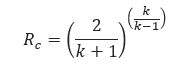
For natural gas this ratio is 0.55.
2. Subsonic Orifice Flow Equation – Subsonic Flow conditions exist where 𝑃2 ≥ 𝑃1𝑅𝐶
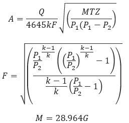
Where
𝐴 − Calculated orfice area(in2)
𝑄 − Flow Rate(ft3/min)
𝑀 − Molecular Weight of Gas
𝐺 − Gas Specific Gravity
𝑇 − Flowing Temperature(°R)
𝑍 − Gas Compressibility Factor
𝑃1 − Pressure(psig)
𝑃2 − Pressure loss through orifice(psi)
3. Sonic Orifice Flow Equation – Sonic Flow conditions exist where 𝑃2 ≥ 𝑃1𝑅𝐶
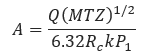
𝐴 − Calculated orfice area(in2)
𝑄 − Flow Rate(ft3/min)
𝑀 − Molecular Weight of Flowing Gas
𝑅𝑐 = Critical Flow Ratio
𝑇 − Flowing Temperature(°R)
𝑘 − Orifice coefficient, use (1/𝐹𝜌𝑣2)
𝑍 − Gas Compressibility Factor for inlet conditions
𝑃1 − Pressure(psig)
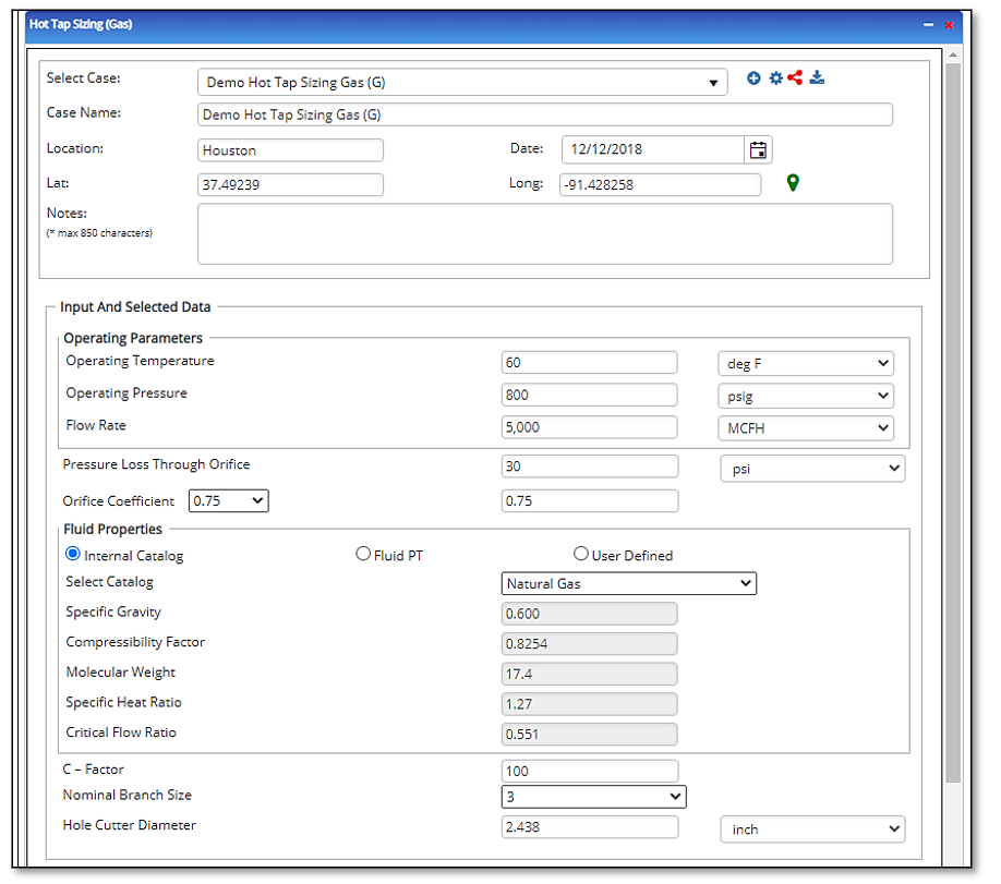
Input Parameters
- To create a new case, click the “Add Case” button
- Select the Hot Tap Sizing application from the Pipeline Facilities section.
- Enter Case Name, Location, Date and any necessary notes.
- Fill out all required fields.
- Make sure the values you are inputting are in the correct units.
- Click the CALCULATE button.
- Molecular Weight
- Specific Heat Ratio
- Critical Flow Ratio
- Nominal Branch Size
- Hole Cutter Diameter(in)
- Pressure(psig)
- Flowing Temperature(°F)
- Pressure Loss Through Orifice(psi)
- Flow Rate(MCFH)
- Orifice Coefficient
- Gas Specific Gravity
- Gas Compressibility Factor
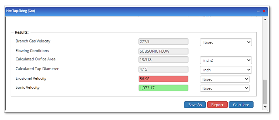
Outputs/Reports
- View the results.
- If an input parameter needs to be edited be sure to hit the CALCULATE button after the change.
- To SAVE, fill out all required case details then click the SAVE button.
- To rename an existing file, click the SAVE As button. Provide all case info then click SAVE.
- To generate a REPORT, click the REPORT button.
- The user may export the Case/Report by clicking the Export to Excel/PowerPoint icon.
- To delete a case, click the DELETE icon near the top of the widget.
- Branch Gas Velocity
- Flowing Conditions
- Calculated Orifice Area(in²)
- Calculated Tap Diameter(in)
Related Links
Table of Contents
Table of Pages
Table of Contents
- Pipeline HUB User Resources
- AC Mitigation PowerTool
- API Inspector's Toolbox
- Horizontal Directional Drilling PowerTool
- Crossings Workflow
- Hydrotest PowerTool
- Pipeline Toolbox
- Encroachment Manager
- PRCI AC Mitigation Toolbox
- PRCI RSTRENG
- RSTRENG+
- Ad-hoc Analysis
- Database Import
- Data Availability Dashboard
- ESRI Map
- Report Builder
- Crossings Workflow
- Hydrotest PowerTool
- Investigative Dig PowerTool
- Hydraulics PowerTool
- External Corrosion Direct Assessment Procedure - RSTRENG
- Canvas
- Definitions
- Pipe Schedule and Specifications Tables