
Introduction
This application calculates the various values associated with gas flow through a regulator, including flow rate, inlet and outlet pressure, differential pressure, outlet velocity, outlet temperature, flow mode, rated and required valve factor, and valve factor ratio. The calculator supports a wide range of industry and manufacturer-specific sizing equations, selecting the appropriate method based on the make and model of the regulator chosen from the catalog.
Note: This calculation considers the regulator only — the effect of upstream, intermediate, or downstream piping is not included. Use the Regulator & Monitor System or Regulator & Relief Valve System calculation routines to include the influence of the associated station piping.
Background
A regulator is a device used to reduce a higher upstream pressure to a lower downstream pressure. Regulators are also referred to as governors, control valves, and pressure-reducing valves (PRVs). In the context of this calculation, a regulator is treated as a device that attempts to maintain a set downstream pressure by reducing a higher upstream pressure to a lower downstream set pressure.
A regulator is essentially an automated valve with a controller that opens and closes the valve as required to maintain the set pressure. The downstream pressure is sensed — either internally or through an external sense line — to determine whether to open or close the valve. The controller can range from a simple spring-and-diaphragm arrangement to a more sophisticated pilot-assisted control system. The calculator does not attempt to model the internal workings of the sense, control, and valve dependencies; the calculation methods consider the nominal operation of the regulator.
In general, the capacity of a regulator is a function of the valve size (valve factor) and the pressure differential across the valve opening. The volume of gas flowing through a regulator can usually be increased by increasing the pressure drop across the opening — either by decreasing the downstream pressure when the upstream pressure is fixed, or by increasing the upstream pressure when the downstream pressure is fixed. The maximum capacity of all regulators is limited by sonic flow through the valve opening, at which point the flow is said to be “choked.” As a rule of thumb, choked flow occurs when the upstream pressure is approximately twice the downstream pressure. Once choked flow is reached, the volume of gas cannot be increased by decreasing the downstream pressure; the upstream pressure must be increased to increase the flow for a given valve size.
Regulator manufacturers provide a variety of equations and formulas to define the relationship between valve size and pressure drop. Most are based on the “universal gas sizing” equation, modified by each manufacturer using assumptions or empirical observations to better describe the behavior of their particular device. Because of this, there is no single equation that can be used to compare the performance of regulators from different manufacturers.
One common parameter across the equations, however, is the “valve factor.” Generally, a larger valve factor indicates greater capacity. However, because the factor is defined and used differently by different manufacturers in different equations, it is only a reliable comparator within the same make and model — not between different makes, or even between different models from the same manufacturer. To compare regulator capacities, it is best to calculate the capacity of each device under similar conditions using the appropriate sizing equation.
The performance of some regulators is not defined by a mathematical equation. In these cases, performance is defined by capacity tables or charts, which the calculator supports through a special-format regulator sizing table. Devices defined by a sizing table are limited to capacity calculations, and the inlet and outlet pressures must fall within the values reported in the table — extrapolation is not supported.
Several simpler regulator designs allow the outlet pressure to drop well below the set pressure under flowing conditions; this phenomenon is referred to as droop. The calculator does account for droop in the Regulator Values calculation.
There are no formal industry standards for sizing regulators beyond ensuring adequate capacity, but a common rule of thumb recommends that the required capacity be no less than 20% and no more than 80% of the rated capacity.
Equations
Regulator Values supports the calculation of values associated with flow through a regulator using a variety of industry and manufacturer-specific equations. The method used is determined by the make and model of the selected device. The supported equations are described below. All pressures in the equations are absolute (psia); gauge pressures are converted via P = Pgauge + Patm, where Patm is the average atmospheric pressure at the regulator location.
American Meter – Reliance
Derived from the cited reference (Reference 17), the American Meter – Reliance flow equation is:
\text{If } P_2 > 0.53\,P_1 \quad (\text{Subsonic})\text{If } P_2 > 0.53\,P_1 \quad (\text{Subsonic})
Q = F_B \times C \times \sqrt{\dfrac{P_2(P_1 - P_2)}{SG}}Q = F_B \times C \times \sqrt{\dfrac{P_2(P_1 – P_2)}{SG}}
\text{If } P_2 \le 0.53\,P_1 \quad (\text{Choked})\text{If } P_2 \le 0.53\,P_1 \quad (\text{Choked})
Q = \dfrac{F_B \times C \times P_1}{2} \times \sqrt{\dfrac{1}{SG}}Q = \dfrac{F_B \times C \times P_1}{2} \times \sqrt{\dfrac{1}{SG}}
F_B = \left(\dfrac{T_B}{520}\right)\left(\dfrac{14.73}{P_B}\right)F_B = \left(\dfrac{T_B}{520}\right)\left(\dfrac{14.73}{P_B}\right)
Where:
Q — Volumetric Flow Rate at the Specified Base Pressure and Temperature, ft3/hr
FB — Base Correction Factor, dimensionless
C — Orifice Constant, ft3/hr·psi
SG — Specific Gravity of Gas, dimensionless
P1 — Pipe Inlet (Upstream) Pressure, psia (= P1,gauge + Patm)
P2 — Pipe Outlet (Downstream) Pressure, psia (= P2,gauge + Patm)
PB — Base Pressure, psia
TB — Base Temperature, °R
American Meter AFV
Suitable for use with American Axial Flow Valve regulators and derived from the cited reference (Reference 2). Note that the American Meter AFV equation is essentially the same as the ISA-S75.01 equation.
\text{If } (P_1 - P_2) < (F_k\,X_t\,P_1) \quad (\text{Subsonic})\text{If } (P_1 – P_2) < (F_k\,X_t\,P_1) \quad (\text{Subsonic})
\begin{aligned}&Q = 1359.792 \times F_B \times C_V \times Y \times \sqrt{\dfrac{P_1^2 - P_1 P_2}{SG \times T_F}}\\[6pt]&Y = 1 - \dfrac{P_1 - P_2}{3 \times F_k \times X_t \times P_1}\end{aligned}\begin{aligned}&Q = 1359.792 \times F_B \times C_V \times Y \times \sqrt{\dfrac{P_1^2 – P_1 P_2}{SG \times T_F}}\\[6pt]&Y = 1 – \dfrac{P_1 – P_2}{3 \times F_k \times X_t \times P_1}\end{aligned}
\text{If } (P_1 - P_2) \ge (F_k\,X_t\,P_1) \quad (\text{Choked})\text{If } (P_1 – P_2) \ge (F_k\,X_t\,P_1) \quad (\text{Choked})
Q = 906.981 \times F_B \times C_V \times P_1 \times \sqrt{\dfrac{F_k \times X_t}{SG \times T_F}}Q = 906.981 \times F_B \times C_V \times P_1 \times \sqrt{\dfrac{F_k \times X_t}{SG \times T_F}}
F_B = \left(\dfrac{T_B}{520}\right)\left(\dfrac{14.73}{P_B}\right)F_B = \left(\dfrac{T_B}{520}\right)\left(\dfrac{14.73}{P_B}\right)
Where:
Q — Volumetric Flow Rate at the Specified Base Pressure and Temperature, ft3/hr
FB — Base Correction Factor, dimensionless
CV — Valve Constant, ft3/hr·psi
Y — Expansion Coefficient, dimensionless
Fk — Specific Heat Ratio Factor, dimensionless
Xt — Critical Flow Factor, dimensionless
SG — Specific Gravity of Gas, dimensionless
TF — Average Gas Flowing Temperature, °R
P1 — Pipe Inlet (Upstream) Pressure, psia (= P1,gauge + Patm)
P2 — Pipe Outlet (Downstream) Pressure, psia (= P2,gauge + Patm)
PB — Base Pressure, psia
TB — Base Temperature, °R
Donkin
Suitable for use with certain model Donkin regulators and derived from the cited reference (Reference 16).
\text{If } \dfrac{P_1}{P_2} < 2 \quad (\text{Subsonic})\text{If } \dfrac{P_1}{P_2} < 2 \quad (\text{Subsonic})
Q = 22.772 \times F_B \times C_g \times P_1 \times \sqrt{\dfrac{1}{SG \times T_F}} \times \sin\!\left(K_1 \sqrt{\dfrac{P_1 - P_2}{P_1}}\right)Q = 22.772 \times F_B \times C_g \times P_1 \times \sqrt{\dfrac{1}{SG \times T_F}} \times \sin\!\left(K_1 \sqrt{\dfrac{P_1 – P_2}{P_1}}\right)
\text{If } \dfrac{P_1}{P_2} \ge 2 \quad (\text{Choked})\text{If } \dfrac{P_1}{P_2} \ge 2 \quad (\text{Choked})
Q = 22.772 \times F_B \times C_g \times P_1 \times \sqrt{\dfrac{1}{SG \times T_F}}Q = 22.772 \times F_B \times C_g \times P_1 \times \sqrt{\dfrac{1}{SG \times T_F}}
F_B = \left(\dfrac{T_B}{518.67}\right)\left(\dfrac{14.696}{P_B}\right)F_B = \left(\dfrac{T_B}{518.67}\right)\left(\dfrac{14.696}{P_B}\right)
Where:
Q — Volumetric Flow Rate at the Specified Base Pressure and Temperature, ft3/hr
FB — Base Correction Factor, dimensionless
Cg — Gas Sizing Coefficient, dimensionless
K1 — Body Shape Factor, dimensionless (assumed constant for a specific size and model)
SG — Specific Gravity of Gas, dimensionless
TF — Average Gas Flowing Temperature, °R
P1 — Pipe Inlet (Upstream) Pressure, psia (= P1,gauge + Patm)
P2 — Pipe Outlet (Downstream) Pressure, psia (= P2,gauge + Patm)
PB — Base Pressure, psia
TB — Base Temperature, °R
Equimeter & Rockwell
Suitable for use with certain models of Equimeter, Sensus, and Rockwell regulators and derived from the cited references (References 3 and 4).
\text{If } \dfrac{P_1}{P_2} < 1.894 \quad (\text{Subsonic})\text{If } \dfrac{P_1}{P_2} < 1.894 \quad (\text{Subsonic})
Q = F_B \times K \times \sqrt{\dfrac{0.6\,P_2(P_1 - P_2)}{SG}}Q = F_B \times K \times \sqrt{\dfrac{0.6\,P_2(P_1 – P_2)}{SG}}
\text{If } \dfrac{P_1}{P_2} \ge 1.894 \quad (\text{Choked})\text{If } \dfrac{P_1}{P_2} \ge 1.894 \quad (\text{Choked})
Q = \dfrac{F_B \times K \times P_1}{2} \times \sqrt{\dfrac{0.6}{SG}}Q = \dfrac{F_B \times K \times P_1}{2} \times \sqrt{\dfrac{0.6}{SG}}
F_B = \left(\dfrac{T_B}{520}\right)\left(\dfrac{14.65}{P_B}\right)F_B = \left(\dfrac{T_B}{520}\right)\left(\dfrac{14.65}{P_B}\right)
Where:
Q — Volumetric Flow Rate at the Specified Base Pressure and Temperature, ft3/hr
FB — Base Correction Factor, dimensionless
K — Regulator Valve Constant, ft3/hr·psi
SG — Specific Gravity of Gas, dimensionless
P1 — Pipe Inlet (Upstream) Pressure, psia (= P1,gauge + Patm)
P2 — Pipe Outlet (Downstream) Pressure, psia (= P2,gauge + Patm)
PB — Base Pressure, psia
TB — Base Temperature, °R
Fisher Controls
Suitable for use with certain models of Fisher Controls regulators and derived from the cited reference (Reference 5).
\text{If } \dfrac{P_2}{P_1} > 0.5 \quad (\text{Subsonic})\text{If } \dfrac{P_2}{P_1} > 0.5 \quad (\text{Subsonic})
Q = F_B \times C_g \times P_1 \times \sqrt{\dfrac{520}{SG \times T_F}} \times \sin\!\left(\dfrac{59.638}{C_1}\sqrt{\dfrac{P_1 - P_2}{P_1}}\right)Q = F_B \times C_g \times P_1 \times \sqrt{\dfrac{520}{SG \times T_F}} \times \sin\!\left(\dfrac{59.638}{C_1}\sqrt{\dfrac{P_1 – P_2}{P_1}}\right)
\text{If } \dfrac{P_2}{P_1} \le 0.5 \quad (\text{Choked})\text{If } \dfrac{P_2}{P_1} \le 0.5 \quad (\text{Choked})
Q = F_B \times C_g \times P_1 \times \sqrt{\dfrac{520}{SG \times T_F}}Q = F_B \times C_g \times P_1 \times \sqrt{\dfrac{520}{SG \times T_F}}
F_B = \left(\dfrac{T_B}{520}\right)\left(\dfrac{14.7}{P_B}\right)F_B = \left(\dfrac{T_B}{520}\right)\left(\dfrac{14.7}{P_B}\right)
Where:
Q — Volumetric Flow Rate at the Specified Base Pressure and Temperature, ft3/hr
FB — Base Correction Factor, dimensionless
Cg — Gas Sizing Coefficient, dimensionless
C1 — Valve Recovery Coefficient, dimensionless (assumed constant for a specific size and model)
SG — Specific Gravity of Gas, dimensionless
TF — Average Gas Flowing Temperature, °R
P1 — Pipe Inlet (Upstream) Pressure, psia (= P1,gauge + Patm)
P2 — Pipe Outlet (Downstream) Pressure, psia (= P2,gauge + Patm)
PB — Base Pressure, psia
TB — Base Temperature, °R
Grove 80
Suitable for use with Grove Model 80 regulators and derived from the cited reference (Reference 6).
\text{If } \dfrac{P_1 - P_2}{P_1} < (F_k\,X_t) \quad (\text{Subsonic})\text{If } \dfrac{P_1 – P_2}{P_1} < (F_k\,X_t) \quad (\text{Subsonic})
Q = 1359 \times F_B \times C \times Y_1 \times \sqrt{\dfrac{P_1(P_1 - P_2)}{SG \times T_F \times Z}}Q = 1359 \times F_B \times C \times Y_1 \times \sqrt{\dfrac{P_1(P_1 – P_2)}{SG \times T_F \times Z}}
\text{If } \dfrac{P_1 - P_2}{P_1} \ge (F_k\,X_t) \quad (\text{Choked})\text{If } \dfrac{P_1 – P_2}{P_1} \ge (F_k\,X_t) \quad (\text{Choked})
Q = 22.8 \times F_B \times C_1 \times C \times P_1 \times \sqrt{\dfrac{F_k}{SG \times T_F \times Z}}Q = 22.8 \times F_B \times C_1 \times C \times P_1 \times \sqrt{\dfrac{F_k}{SG \times T_F \times Z}}
The partially open capacity factor C, critical flow factor C1, and expansion coefficient Y1 are defined as follows:
\begin{aligned}&C = \begin{cases} 0, & P_1 - P_2 \le 0.8E \\[2pt] C_p\!\left(\dfrac{(P_1 - P_2) - 0.8E}{1.2E}\right), & 0.8E < P_1 - P_2 < 2E \\[6pt] C_p, & P_1 - P_2 \ge 2E \end{cases}\\[12pt]&C_1 = 9.253 + 49.171\,X_t - 27.268\,X_t^2 + 8.586\,X_t^3\\[12pt]&Y_1 = \begin{cases} 1, & \dfrac{P_1 - P_2}{P_1} \le 0.02 \\[6pt] 1 - \dfrac{0.333(P_1 - P_2)}{X_t \times P_1 \times F_k}, & 0.02 < \dfrac{P_1 - P_2}{P_1} < (X_t \times F_k) \\[6pt] 0.667, & \dfrac{P_1 - P_2}{P_1} \ge (X_t \times F_k) \end{cases}\end{aligned}\begin{aligned}&C = \begin{cases} 0, & P_1 – P_2 \le 0.8E \\[2pt] C_p\!\left(\dfrac{(P_1 – P_2) – 0.8E}{1.2E}\right), & 0.8E < P_1 – P_2 < 2E \\[6pt] C_p, & P_1 – P_2 \ge 2E \end{cases}\\[12pt]&C_1 = 9.253 + 49.171\,X_t – 27.268\,X_t^2 + 8.586\,X_t^3\\[12pt]&Y_1 = \begin{cases} 1, & \dfrac{P_1 – P_2}{P_1} \le 0.02 \\[6pt] 1 – \dfrac{0.333(P_1 – P_2)}{X_t \times P_1 \times F_k}, & 0.02 < \dfrac{P_1 – P_2}{P_1} < (X_t \times F_k) \\[6pt] 0.667, & \dfrac{P_1 – P_2}{P_1} \ge (X_t \times F_k) \end{cases}\end{aligned}
F_B = \left(\dfrac{T_B}{520}\right)\left(\dfrac{14.7}{P_B}\right)F_B = \left(\dfrac{T_B}{520}\right)\left(\dfrac{14.7}{P_B}\right)
Where:
Q — Volumetric Flow Rate at the Specified Base Pressure and Temperature, ft3/hr
FB — Base Correction Factor, dimensionless
C — Partially Open Capacity Factor, dimensionless
C1 — Critical Flow Factor, dimensionless
Cp — Valve Wide-Open Capacity Coefficient, dimensionless
E — Tube Expansion Factor, dimensionless
Fk — Specific Heat Ratio Factor, dimensionless
Xt — Critical Pressure Drop Ratio, dimensionless
Y1 — Expansion Coefficient, dimensionless
Z — Compressibility Factor, dimensionless (if the specific gravity is between 0.5 and 0.6, interpolated from the manufacturer’s literature, otherwise equal to 1.0)
SG — Specific Gravity of Gas, dimensionless
TF — Average Gas Flowing Temperature, °R
P1 — Pipe Inlet (Upstream) Pressure, psia (= P1,gauge + Patm)
P2 — Pipe Outlet (Downstream) Pressure, psia (= P2,gauge + Patm)
PB — Base Pressure, psia
TB — Base Temperature, °R
Grove 83
Suitable for use with Grove Model 83 Flexflo regulators and derived from the cited reference (Reference 15). The flow rate is given by the following expression, with the differential pressure DP, expansion coefficient Y, and base correction factor FB defined individually below.
Q = 1359\,F_B \times C_V \times A \times Y \times \sqrt{\dfrac{DP}{SG \times T_F \times Z}}Q = 1359\,F_B \times C_V \times A \times Y \times \sqrt{\dfrac{DP}{SG \times T_F \times Z}}
\text{If } \dfrac{P_1 - P_2}{P_1} < X_t\,F_k \quad (\text{Subsonic})\text{If } \dfrac{P_1 – P_2}{P_1} < X_t\,F_k \quad (\text{Subsonic})
DP = P_1(P_1 - P_2)
DP = P_1(P_1 – P_2)
\text{If } \dfrac{P_1 - P_2}{P_1} \ge X_t\,F_k \quad (\text{Choked})\text{If } \dfrac{P_1 – P_2}{P_1} \ge X_t\,F_k \quad (\text{Choked})
DP = X_t\,F_k
DP = X_t\,F_k
Y = \begin{cases} 1.0, & \dfrac{P_1 - P_2}{P_1} < 0.02 \\[4pt] 1 - \dfrac{0.342(P_1 - P_2)}{X_t F_k P_1}, & \dfrac{P_1 - P_2}{P_1} \le 0.975\,X_t F_k \\[4pt] 0.667, & \dfrac{P_1 - P_2}{P_1} > 0.975\,X_t F_k \end{cases}Y = \begin{cases} 1.0, & \dfrac{P_1 – P_2}{P_1} < 0.02 \\[4pt] 1 – \dfrac{0.342(P_1 – P_2)}{X_t F_k P_1}, & \dfrac{P_1 – P_2}{P_1} \le 0.975\,X_t F_k \\[4pt] 0.667, & \dfrac{P_1 – P_2}{P_1} > 0.975\,X_t F_k \end{cases}
F_B = \left(\dfrac{T_B}{520}\right)\left(\dfrac{14.7}{P_B}\right)F_B = \left(\dfrac{T_B}{520}\right)\left(\dfrac{14.7}{P_B}\right)
Where:
Q — Volumetric Flow Rate at the Specified Base Pressure and Temperature, ft3/hr
FB — Base Correction Factor, dimensionless
CV — Valve Capacity Factor, dimensionless
A — Valve Opening Factor, dimensionless (interpolated from the manufacturer’s literature if a code is present, otherwise equal to 1.0)
Y — Expansion Coefficient, dimensionless (as defined above)
DP — Differential Pressure Term, psia2
Fk — Specific Heat Ratio Factor, dimensionless
Xt — Critical Pressure Drop Ratio, dimensionless
Z — Supercompressibility Factor, dimensionless (if the specific gravity is between 0.5 and 0.6, interpolated from the manufacturer’s literature, otherwise equal to 1.0)
SG — Specific Gravity of Gas, dimensionless
TF — Average Gas Flowing Temperature, °R
P1 — Pipe Inlet (Upstream) Pressure, psia (= P1,gauge + Patm)
P2 — Pipe Outlet (Downstream) Pressure, psia (= P2,gauge + Patm)
PB — Base Pressure, psia
TB — Base Temperature, °R
Grove 900
Suitable for use with Grove Model 900TE Flexflo regulators and derived from the cited references (References 7, 8, and 14).
\text{If } \dfrac{P_1 - P_2}{P_1} < X_t\,F_k \quad (\text{Subsonic})\text{If } \dfrac{P_1 – P_2}{P_1} < X_t\,F_k \quad (\text{Subsonic})
\begin{aligned}&Q = 1359\,F_B \times C_V \times A \times Y \times \sqrt{\dfrac{DP}{SG \times T_F \times Z}}\\[6pt]&DP = P_1(P_1 - P_2), \qquad Y = 1 - \dfrac{P_1 - P_2}{3\,X_t F_k P_1}\end{aligned}\begin{aligned}&Q = 1359\,F_B \times C_V \times A \times Y \times \sqrt{\dfrac{DP}{SG \times T_F \times Z}}\\[6pt]&DP = P_1(P_1 – P_2), \qquad Y = 1 – \dfrac{P_1 – P_2}{3\,X_t F_k P_1}\end{aligned}
\text{If } \dfrac{P_1 - P_2}{P_1} \ge X_t\,F_k \quad (\text{Choked})\text{If } \dfrac{P_1 – P_2}{P_1} \ge X_t\,F_k \quad (\text{Choked})
\begin{aligned}&Q = 1359\,F_B \times C_V \times A \times Y \times \sqrt{\dfrac{DP}{SG \times T_F \times Z}}\\[6pt]&DP = X_t\,F_k, \qquad Y = 0.667\end{aligned}\begin{aligned}&Q = 1359\,F_B \times C_V \times A \times Y \times \sqrt{\dfrac{DP}{SG \times T_F \times Z}}\\[6pt]&DP = X_t\,F_k, \qquad Y = 0.667\end{aligned}
F_B = \left(\dfrac{T_B}{520}\right)\left(\dfrac{14.7}{P_B}\right)F_B = \left(\dfrac{T_B}{520}\right)\left(\dfrac{14.7}{P_B}\right)
Where:
Q — Volumetric Flow Rate at the Specified Base Pressure and Temperature, ft3/hr
FB — Base Correction Factor, dimensionless
CV — Valve Capacity Factor, dimensionless
A — Valve Opening Factor, dimensionless (interpolated from the manufacturer’s literature if a code is present, otherwise equal to 1.0)
Y — Expansion Coefficient, dimensionless
DP — Differential Pressure Term, psia2
Fk — Specific Heat Ratio Factor, dimensionless
Xt — Critical Pressure Drop Ratio, dimensionless
Z — Supercompressibility Factor, dimensionless (if the specific gravity is between 0.5 and 0.6, interpolated from the manufacturer’s literature, otherwise equal to 1.0)
SG — Specific Gravity of Gas, dimensionless
TF — Average Gas Flowing Temperature, °R
P1 — Pipe Inlet (Upstream) Pressure, psia (= P1,gauge + Patm)
P2 — Pipe Outlet (Downstream) Pressure, psia (= P2,gauge + Patm)
PB — Base Pressure, psia
TB — Base Temperature, °R
ISA-S75.01
This method uses the equations described in Instrument Society of America Standard ISA-S75.01-1985, “Flow Equations for Sizing Control Valves” (Revised 1995). It is suitable for use with regulators stated as compliant with this standard that provide suitable sizing parameters. The ISA-S75.01 equation is essentially the same as the American Meter AFV equation shown above.
Itron
Suitable for use with certain models of Itron regulators and derived from the cited reference (Reference 13).
\text{If } \dfrac{P_1}{P_2} < 1.894 \quad (\text{Subsonic})\text{If } \dfrac{P_1}{P_2} < 1.894 \quad (\text{Subsonic})
Q = F_B \times K \times \sqrt{\dfrac{0.6\,P_2(P_1 - P_2)}{SG}}Q = F_B \times K \times \sqrt{\dfrac{0.6\,P_2(P_1 – P_2)}{SG}}
\text{If } \dfrac{P_1}{P_2} \ge 1.894 \quad (\text{Choked})\text{If } \dfrac{P_1}{P_2} \ge 1.894 \quad (\text{Choked})
Q = \dfrac{F_B \times K \times P_1}{2} \times \sqrt{\dfrac{0.6}{SG}}Q = \dfrac{F_B \times K \times P_1}{2} \times \sqrt{\dfrac{0.6}{SG}}
F_B = \left(\dfrac{T_B}{520}\right)\left(\dfrac{14.7}{P_B}\right)F_B = \left(\dfrac{T_B}{520}\right)\left(\dfrac{14.7}{P_B}\right)
Where:
Q — Volumetric Flow Rate at the Specified Base Pressure and Temperature, ft3/hr
FB — Base Correction Factor, dimensionless
K — Orifice Coefficient, ft3/hr·psi
SG — Specific Gravity of Gas, dimensionless
P1 — Pipe Inlet (Upstream) Pressure, psia (= P1,gauge + Patm)
P2 — Pipe Outlet (Downstream) Pressure, psia (= P2,gauge + Patm)
PB — Base Pressure, psia
TB — Base Temperature, °R
Mokveld
Suitable for use with Mokveld Valve regulators and derived from the cited reference (Reference 12). This method uses a single flow equation across all pressure conditions.
\begin{aligned}&Q = 832.9438 \times F_B \times F_L \times C_V \times P_1 \times \left(Y - 0.148\,Y^3\right) \times \dfrac{1}{\sqrt{SG \times T_F}}\\[10pt]&Y = \dfrac{1.63}{F_L}\sqrt{\dfrac{P_1 - P_2}{P_1}}, \qquad Y \le 1.5\end{aligned}\begin{aligned}&Q = 832.9438 \times F_B \times F_L \times C_V \times P_1 \times \left(Y – 0.148\,Y^3\right) \times \dfrac{1}{\sqrt{SG \times T_F}}\\[10pt]&Y = \dfrac{1.63}{F_L}\sqrt{\dfrac{P_1 – P_2}{P_1}}, \qquad Y \le 1.5\end{aligned}
F_B = \left(\dfrac{T_B}{518.67}\right)\left(\dfrac{14.69}{P_B}\right)F_B = \left(\dfrac{T_B}{518.67}\right)\left(\dfrac{14.69}{P_B}\right)
Where:
Q — Volumetric Flow Rate at the Specified Base Pressure and Temperature, ft3/hr
FB — Base Correction Factor, dimensionless
FL — Valve Recovery Coefficient, dimensionless
CV — Valve Capacity Coefficient, ft3/hr·psi
Y — Expansion Term, dimensionless (capped at 1.5)
SG — Specific Gravity of Gas, dimensionless
TF — Average Gas Flowing Temperature, °R
P1 — Pipe Inlet (Upstream) Pressure, psia (= P1,gauge + Patm)
P2 — Pipe Outlet (Downstream) Pressure, psia (= P2,gauge + Patm)
PB — Base Pressure, psia
TB — Base Temperature, °R
Mooney Controls
Suitable for use with Mooney Controls regulators and derived from the cited reference (Reference 9).
\text{If } \dfrac{P_1 - P_2}{P_2} < 0.64 \quad (\text{Subsonic})\text{If } \dfrac{P_1 – P_2}{P_2} < 0.64 \quad (\text{Subsonic})
Q = F_B \times C_g \times P_1 \times \sqrt{\dfrac{520}{SG \times T_F}} \times \sin\!\left(\dfrac{59.638}{C_1}\sqrt{\dfrac{P_1 - P_2}{P_1}}\right)Q = F_B \times C_g \times P_1 \times \sqrt{\dfrac{520}{SG \times T_F}} \times \sin\!\left(\dfrac{59.638}{C_1}\sqrt{\dfrac{P_1 – P_2}{P_1}}\right)
\text{If } \dfrac{P_1 - P_2}{P_2} \ge 0.64 \quad (\text{Choked})\text{If } \dfrac{P_1 – P_2}{P_2} \ge 0.64 \quad (\text{Choked})
Q = F_B \times C_g \times P_1 \times \sqrt{\dfrac{520}{SG \times T_F}}Q = F_B \times C_g \times P_1 \times \sqrt{\dfrac{520}{SG \times T_F}}
F_B = \left(\dfrac{T_B}{520}\right)\left(\dfrac{14.7}{P_B}\right)F_B = \left(\dfrac{T_B}{520}\right)\left(\dfrac{14.7}{P_B}\right)
Where:
Q — Volumetric Flow Rate at the Specified Base Pressure and Temperature, ft3/hr
FB — Base Correction Factor, dimensionless
Cg — Gas Sizing Coefficient, dimensionless
C1 — Valve Recovery Coefficient, dimensionless
SG — Specific Gravity of Gas, dimensionless
TF — Average Gas Flowing Temperature, °R
P1 — Pipe Inlet (Upstream) Pressure, psia (= P1,gauge + Patm)
P2 — Pipe Outlet (Downstream) Pressure, psia (= P2,gauge + Patm)
PB — Base Pressure, psia
TB — Base Temperature, °R
Pietro Fiorentini
Suitable for use with certain model Pietro Fiorentini regulators and derived from the cited reference (Reference 10).
\text{If } \dfrac{P_1}{P_2} < 2 \quad (\text{Subsonic})\text{If } \dfrac{P_1}{P_2} < 2 \quad (\text{Subsonic})
Q = 22.77972 \times F_B \times C_g \times P_1 \times \sqrt{\dfrac{1}{SG \times T_F}} \times \sin\!\left(K_1 \sqrt{\dfrac{P_1 - P_2}{P_1}}\right)Q = 22.77972 \times F_B \times C_g \times P_1 \times \sqrt{\dfrac{1}{SG \times T_F}} \times \sin\!\left(K_1 \sqrt{\dfrac{P_1 – P_2}{P_1}}\right)
\text{If } \dfrac{P_1}{P_2} \ge 2 \quad (\text{Choked})\text{If } \dfrac{P_1}{P_2} \ge 2 \quad (\text{Choked})
Q = 22.77972 \times F_B \times C_g \times P_1 \times \sqrt{\dfrac{1}{SG \times T_F}}Q = 22.77972 \times F_B \times C_g \times P_1 \times \sqrt{\dfrac{1}{SG \times T_F}}
F_B = \left(\dfrac{T_B}{519}\right)\left(\dfrac{14.692}{P_B}\right)F_B = \left(\dfrac{T_B}{519}\right)\left(\dfrac{14.692}{P_B}\right)
Where:
Q — Volumetric Flow Rate at the Specified Base Pressure and Temperature, ft3/hr
FB — Base Correction Factor, dimensionless
Cg — Valve Coefficient, dimensionless
K1 — Body Shape Factor, dimensionless (assumed constant for a specific size and model)
SG — Specific Gravity of Gas, dimensionless
TF — Average Gas Flowing Temperature, °R
P1 — Pipe Inlet (Upstream) Pressure, psia (= P1,gauge + Patm)
P2 — Pipe Outlet (Downstream) Pressure, psia (= P2,gauge + Patm)
PB — Base Pressure, psia
TB — Base Temperature, °R
Universal
The original universal gas sizing equation, derived from the cited reference (Reference 11). The flow uses a single expression with the term SIN(X) evaluated by flow regime:
Q = F_B \times C_1 \times C_2 \times C_V \times P_1 \times \sqrt{\dfrac{520}{SG \times T_F}} \times \mathrm{SIN}(X)Q = F_B \times C_1 \times C_2 \times C_V \times P_1 \times \sqrt{\dfrac{520}{SG \times T_F}} \times \mathrm{SIN}(X)
C_1 = \dfrac{C_g}{C_V}, \qquad C_2 = \dfrac{\sqrt{\dfrac{k}{k+1}\left(\dfrac{2}{k+1}\right)^{\frac{2}{k-1}}}}{0.4839}, \qquad X = \dfrac{59.64}{C_1 C_2}\sqrt{\dfrac{P_1 - P_2}{P_1}}C_1 = \dfrac{C_g}{C_V}, \qquad C_2 = \dfrac{\sqrt{\dfrac{k}{k+1}\left(\dfrac{2}{k+1}\right)^{\frac{2}{k-1}}}}{0.4839}, \qquad X = \dfrac{59.64}{C_1 C_2}\sqrt{\dfrac{P_1 – P_2}{P_1}}
\text{If } X < \dfrac{\pi}{2} \quad (\text{Subsonic})\text{If } X < \dfrac{\pi}{2} \quad (\text{Subsonic})
\mathrm{SIN}(X) = \sin(X)\mathrm{SIN}(X) = \sin(X)
\text{If } X \ge \dfrac{\pi}{2} \quad (\text{Choked})\text{If } X \ge \dfrac{\pi}{2} \quad (\text{Choked})
\mathrm{SIN}(X) = 1.0\mathrm{SIN}(X) = 1.0
F_B = \left(\dfrac{T_B}{520}\right)\left(\dfrac{14.7}{P_B}\right)F_B = \left(\dfrac{T_B}{520}\right)\left(\dfrac{14.7}{P_B}\right)
Where:
Q — Volumetric Flow Rate at the Specified Base Pressure and Temperature, ft3/hr
FB — Base Correction Factor, dimensionless
C1 — Valve Recovery Coefficient, dimensionless
C2 — Sizing Coefficient Term, dimensionless
Cg — Gas Sizing Coefficient, dimensionless
CV — Flow Coefficient (Liquid Sizing Coefficient), ft3/hr·psi
k — Specific Heat Ratio, dimensionless
X — Sizing Argument, dimensionless
SG — Specific Gravity of Gas, dimensionless
TF — Average Gas Flowing Temperature, °R
P1 — Pipe Inlet (Upstream) Pressure, psia (= P1,gauge + Patm)
P2 — Pipe Outlet (Downstream) Pressure, psia (= P2,gauge + Patm)
PB — Base Pressure, psia
TB — Base Temperature, °R
Case Guide
Part 1: Create Case
- Select the Regulator Values application from the Valves & Fittings Module.
- Click the Clear command button to set all values to an empty (null) value.
- Click the Base Conditions command button. Set the base pressure, base temperature, gas properties file, atmospheric pressure method, and compressibility factor method, then click Apply.
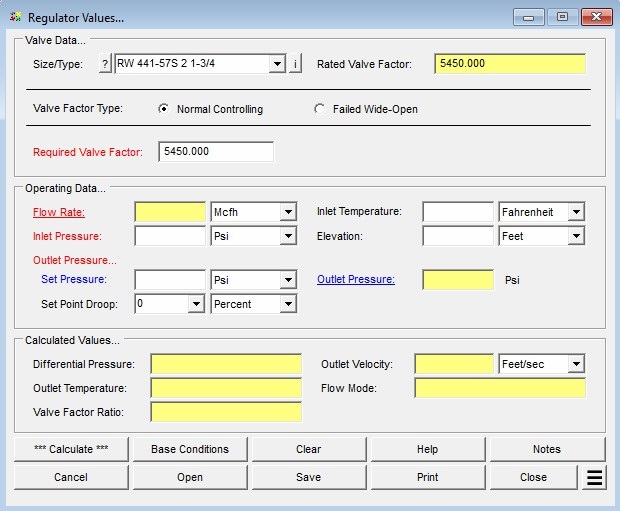
- In the Valve Data section, click the ? command button next to Size/Type to open the Device Selection screen and choose the desired regulator (Manufacturer, Model, Body Size, Orifice Size). The Rated and Required Valve Factors will be populated automatically from the Regulator Property Table.
- Set the Valve Factor Type (Normal Controlling or Failed Wide-Open). The Required Valve Factor may be overwritten with a user-specified value if needed.
- Click on the red label of the item to be solved (the “unknown”) until it is underlined. If a blue label is displayed, click it until underlined. Only one item may be designated as the unknown at a time — all remaining colored-label items must be known.
- Select the desired dimensional units for all data items.
- Enter values for all known parameters in the Operating Data section (Inlet Pressure, Inlet Temperature, Elevation, Set Pressure, Set Point Droop, etc.).
- Click the Calculate command button to compute results.
Input Parameters
| Parameter | Description |
|---|---|
| Size/Type | The regulator Size/Type code. Click the ? command button to select a device using the Device Selection screen. Selecting a device automatically loads the associated Rated and Required Valve Factors from the Regulator Property Table. |
| Valve Factor Type | Specifies whether to use the controlling (Normal Controlling) or Failed Wide-Open valve factor for the device during the calculation. |
| Required Valve Factor | The required valve factor for the regulator. Automatically populated when a Size/Type is selected; may be overwritten by the user. |
| Flow Rate | The gas flow rate through the regulator at standard base conditions. Can be specified as the unknown to be solved. |
| Inlet Pressure | The gauge pressure on the inlet (upstream) side of the regulator. Can be specified as the unknown to be solved. |
| Outlet Pressure | The gauge pressure on the outlet (downstream) side of the regulator. Depending on the Set Point Droop value, it may or may not match the Set Pressure. Can be specified as the unknown to be solved. |
| Set Pressure | The set pressure for the regulator. |
| Set Point Droop | The reduction in the set pressure under maximum flowing conditions. May be expressed as a percentage or in pressure units. |
| Inlet Temperature | The flowing temperature of the gas at the inlet (upstream) side of the regulator. |
| Elevation | The height above mean sea level at the regulator location. Displayed when the Atmospheric Pressure Method in Base Conditions is not set to “None” or “None – Entered Value”. |
| Atm Pressure | The atmospheric pressure at the regulator location. Displayed only when the Atmospheric Pressure Method in Base Conditions is set to “None – Entered Value”. |
Part 2: Outputs/Reports
- If you need to modify an input parameter, click the CALCULATE button after the change.
- To SAVE, fill out all required case details then click the SAVE button.
- To rename an existing file, click the SAVE As button. Provide all case info then click SAVE.
- To generate a REPORT, click the REPORT button.
- The user may export the Case/Report by clicking the Export to Excel icon.
- To delete a case, click the DELETE icon near the top of the widget.
Results
| Output | Description |
|---|---|
| Rated Valve Factor | The rated (published) valve sizing factor for the selected regulator, assigned when a device is chosen from the Size/Type list. |
| Flow Rate | The gas flow rate through the regulator at standard base conditions. Can be specified as the unknown to be solved. |
| Inlet Pressure | The gauge pressure on the inlet (upstream) side of the regulator. Can be specified as the unknown to be solved. |
| Required Valve Factor | The valve factor required to pass the specified flow at the given conditions. Compared against the Rated Valve Factor to determine adequacy. |
| Differential Pressure | The calculated linear pressure difference across the regulator. If less than the required minimum value listed in the Regulator Property Table, the value is displayed in red. |
| Outlet Pressure | The calculated gauge pressure at the outlet (downstream) side of the regulator. |
| Outlet Velocity | The calculated gas velocity at the regulator outlet, computed from the calculated or specified flow rate, the outlet temperature, the outlet pressure, and the listed body size. |
| Outlet Temperature | The estimated gas temperature at the outlet, calculated using the Joule-Thomson method (valid for high-methane-content gases). |
| Flow Mode | The flow mode for the regulator (e.g., Sonic – Critical Flow or subsonic). |
| Valve Factor Ratio | The ratio of the Required Valve Factor to the Rated Valve Factor, expressed as a percentage. A value of 100% indicates the selected regulator is operating at its rated capacity. |
References
- American Meter Company, Regulator Bulletin – Model 1200, SB-8505.1.
- American Meter Company, Axial Flow Valves Capacity Tables, TDB 9610.5.
- Equimeter Inc, Bulletin Model 441-57S, R-1360 Rev 4.
- Rockwell International, Bulletin Model 441-57S, R 1360 Rev 3.
- Fisher Controls, Catalog 10 – Sizing and Selection Data.
- Grove Publication Sk-4-149, Grove Model 80 Flexflo.
- Grove Model 900 TE, Bulletin 900 TE 1 R1, 8/94.
- Instrument Society of America Standard ISA-S75.01-1985, “Flow Equations for Sizing Control Valves”, Revised 1995.
- Mooney Controls, Sizing – Compressible Gases.
- Pietro Fiorentini, Sizing Pressure Regulators & Control Valves, 2010.
- Instrument Society of America Transactions, The Development Of A Universal Gas Sizing Equation For Control Valves, Barish and Schumer, 1964.
- Mokveld Valves, Self-Acting Regulators, 2012.
- Itron Gas, CL38 Regulator, Publication 101077SP-01, 2010.
- Grove Flexsize Regulator Sizing Software, Version 3.0.0.1, 2003.
- Grove Model 83 Flexflo, Bulletin No. 83-Size, 11/94.
- Bryan Donkin Gas Controls Limited, Gas Pressure Regulator Series 270 MK2, Technical Data, R.270.00.698.
- Singer – American Meter Division, Reliance Type HPR Pressure Regulators, Bulletin 120.1, 12-73.
FAQ
-
What type of station does the Regulator & Monitor System calculator model?
The calculator models a two-stage (monitor-style) regulator and relief valve station in which gas pressure is reduced sequentially across two independent regulator stages. Each stage has its own relief valve and vent stack. This configuration is commonly used when codes require automatic overpressure protection at both stages of pressure reduction.
-
Which regulatory codes does this calculator support for compliance checks?
The calculator supports two regulatory codes for compliance checks: US DOT 49 CFR Part 192 (2019 edition) and ASME B31.8 (2007 edition). When a code is selected, the calculator compares the maximum calculated pressure in each piping section against the user-specified MAOP for that section using the allowable limits defined by that code. Results that exceed the allowable limits are highlighted in red on the Compliance data tab.
You can also select “None” to perform the hydraulic and flow calculations without any code-based compliance checking.
-
What information do I need before running this calculator?
Before running the calculator, you will need the following for each stage of the station:
For the supply piping, you need the minimum and maximum inlet pressures, the flowing gas temperature, the pipe and fitting specifications (size, wall thickness, length), and the pipe flow equation and efficiency. For each regulator, you need to select the manufacturer and model from the device database and enter the set pressure. For each relief valve, you need to select the model, enter the set pressure, minimum build-up pressure, and number of installed valves. For the vent stacks, you need the pipe and fitting specifications and whether the outlet discharges to atmosphere.
You will also need the gas composition or a gas properties file, base conditions (pressure and temperature), the minimum and maximum outlet flow rates, and — if performing compliance checks — the MAOP for each of the five piping sections: Upstream (Supply 1), Intermediate 1, Upstream (Supply 2), Intermediate 2, and Outlet.
-
What operating modes does the calculator support, and when should I use each one?
The calculator supports six operating modes, each representing a different assumption about which regulators are operating normally and which have failed.
Use Failed Upstream or Failed Downstream when you want to evaluate a single regulator failure while the other stage operates normally — these are the most common code-required failure scenarios. Use Failed Single to evaluate each regulator failing independently in two separate analyses. Use Failed Double to evaluate simultaneous failure of both regulators, which is the most conservative failure case. Use Normal to verify pressures and velocities under steady-state operation, and Normal Maximum to calculate the maximum flow capacity the combined station can deliver.
-
How does the calculator determine the inlet pressure to the second-stage supply piping?
The inlet pressure to the second-stage supply piping is not a direct user input — it is calculated internally based on the selected operating mode.
In most failure modes (Failed Single, Failed Double, Failed Downstream, Normal, and Normal Maximum), the second-stage inlet pressure is set equal to the first-stage regulator set pressure minus the pressure drop across the first-stage intermediate piping. In the Failed Upstream mode, however, the second-stage inlet pressure is instead set to the calculated build-up pressure at the outlet of the first-stage intermediate piping. This build-up pressure may be higher than the set pressure, since the first-stage relief valve is actively venting and the intermediate piping is operating under overpressure conditions. This distinction is important for correctly sizing the second-stage components in a failed upstream scenario.
-
What does the Relief Branch – First fitting do, and when should I use it?
In most physical installations, the relief valve is not installed inline with the intermediate piping — it is connected via a branch tee. This means the piping upstream of the tee carries both the relief valve flow and any downstream system flow, while the branch piping leading to the relief valve carries only the relief valve flow.
The Relief Branch – First component is a special fitting you add to the intermediate piping component list to tell the calculator where this branch point occurs. The calculator automatically splits the flow at that point: combined flow upstream of the component, relief-valve-only flow downstream. A Relief Branch – Second component is also available for installations with multiple identical relief valves sharing a common header, and is used to mark the point where the header splits to each individual valve.
-
What does the Operating Status field on the Relief Valve data tab mean?
The Operating Status field shows how the relief valve is responding under the calculated conditions. A status of Popping means the inlet pressure has reached or exceeded the relief valve set pressure and the valve is actively venting gas through the vent stack. A status of Continuously Closed means the inlet pressure is below the set pressure and the valve remains shut — no flow passes through the stack piping under those conditions.
In a failure scenario, you want to see Popping on the stage whose regulator has failed, which confirms the relief valve has opened and is handling the failed-regulator flow. If the relief valve is Continuously Closed when it should be venting, the relief valve may be undersized or the set pressure may be too high relative to the build-up pressure.
-
Is the 75% SMYS limit from DOT 192 §192.201(a)(2)(i) checked automatically?
No. When using the US DOT Part 192 regulatory code, the calculator performs MAOP-based compliance checks for each piping section, but it does not automatically evaluate the 75% SMYS hoop stress limit associated with §192.201(a)(2)(i).
If your calculated failed pressures are approaching the MAOP of any section — particularly on higher-pressure upstream piping — you should independently verify the resulting hoop stress using the Hoop Stress calculation routine in the Design & Stress Analysis module to confirm compliance with that limit.