
The Line Heater calculator sizes an inline gas heater installed upstream of a pressure-reducing device such as a regulator. Given the gas flow rate, inlet and outlet pressures, current inlet temperature, and required outlet temperature, the calculator determines the heater rating needed to prevent hydrate formation downstream of the pressure reduction. It can also solve for volumetric flow rate, heater efficiency, heat required, fuel consumption, and heater outlet temperature depending on which value is designated as the unknown.
For detailed heater design and operating performance, the line heater manufacturer should be consulted.
Background
When a gas stream undergoes pressure reduction — for example, flowing through a regulator or an orifice — the gas temperature drops due to the Joule-Thomson effect. In long pipeline segments, the surrounding environment can partially offset this cooling. But across a short pressure-reducing device, the temperature drop is sharp and immediate, leaving no time for heat recovery from the surrounding soil or ambient air.
If water vapor is present in the gas stream, this rapid temperature drop creates a high risk of hydrate formation. Hydrates are ice-like solid compounds of water and hydrocarbon gas molecules that can form at temperatures above 32 °F (0 °C) when the pipeline is at elevated pressure. Hydrate build-up in equipment or instruments located downstream of a pressure reduction point can restrict or completely stop gas flow.
One of the most effective strategies to counteract this risk is to heat the gas stream immediately upstream of the pressure-reducing device using an inline line heater. The heater raises the gas temperature sufficiently so that, after the Joule-Thomson temperature drop across the regulator, the outlet temperature still remains above the hydrate formation temperature.
A common type of inline heater uses a shell-and-tube heat exchanger installed directly in the gas flow path, with pipeline gas as the fuel source. These heaters are typically rated in Btu/hr — the maximum rate at which heat can be transferred to the gas stream. Most pipeline pressure reduction processes are isenthalpic, meaning the energy state of the gas is conserved through the device, which allows the required heat input to be estimated from inlet and outlet conditions alone.
Equations
Heat Required
The input energy requirement for the heater is:
q = HR \times \eta_{th}q = HR \times \eta_{th}
Where:
q − Heat required (Btu/hr)
HR − Line heater rating (Btu/hr)
ηth − Line heater thermodynamic efficiency
Fuel Consumption
Fuel consumption is calculated as:
FC = HR \times HV
FC = HR \times HV
Where:
FC − Fuel consumption (cfh)
HR − Line heater rating (Btu/hr)
HV − Heating value of fuel gas (Btu/cf)
Heater Outlet Temperature
The required temperature of the gas exiting the heater — accounting for the Joule-Thomson temperature drop across the downstream device — is:
T_{out} = \mu_{JT} \times (P_1 - P_2) + T_2T_{out} = \mu_{JT} \times (P_1 – P_2) + T_2
Where:
Tout − Heater outlet gas temperature (Rankine)
μJT − Joule-Thomson coefficient (dimensionless)
P1 − Device inlet pressure (psia)
P2 − Device outlet pressure (psia)
T2 − Required gas temperature at the device outlet (°R)
Heater Rating — Enthalpy Methods
When using either the Theoretic (Calculated Enthalpy) or Theoretic (Entered Enthalpy) method to solve for volumetric flow rate, heater rating, or efficiency, the following system of equations is solved simultaneously:
\frac{Q_F}{Q_B} = \frac{P_B}{P_F} \times \frac{T_F}{T_B} \times \frac{Z_F}{Z_B}\frac{Q_F}{Q_B} = \frac{P_B}{P_F} \times \frac{T_F}{T_B} \times \frac{Z_F}{Z_B}
HR = \frac{\dot{M} \times (H_2 - H_1)}{\eta_{th}}HR = \frac{\dot{M} \times (H_2 – H_1)}{\eta_{th}}
\dot{M} = Q_F \times \rho\dot{M} = Q_F \times \rho
Where:
QF − Volumetric flow rate at flowing pressure and temperature (cfh)
QB − Volumetric flow rate at base conditions (cfh)
PB − Base pressure (psia)
PF − Average flowing pressure (psia)
TF − Average flowing temperature (°R)
TB − Base temperature (°R)
ZF − Compressibility factor at P1
ZB − Compressibility factor at base conditions
HR − Line heater rating (Btu/hr)
Ṁ − Mass flow rate (lbm/hr)
H1 − Heater inlet gas enthalpy (Btu/lbm)
H2 − Heater outlet gas enthalpy (Btu/lbm)
ηth − Line heater thermodynamic efficiency
ρ − Gas density (lbm/cf)
Heater Rating — Specific Heat Method
When using the Theoretic (Entered Specific Heat) method, the heater rating equation substitutes specific heat and temperature rise for the enthalpy difference:
\frac{Q_F}{Q_B} = \frac{P_B}{P_F} \times \frac{T_F}{T_B} \times \frac{Z_F}{Z_B}\frac{Q_F}{Q_B} = \frac{P_B}{P_F} \times \frac{T_F}{T_B} \times \frac{Z_F}{Z_B}
HR = \frac{\dot{M} \times C_p \times (T_2 - T_1)}{\eta_{th}}HR = \frac{\dot{M} \times C_p \times (T_2 – T_1)}{\eta_{th}}
\dot{M} = Q_F \times \rho\dot{M} = Q_F \times \rho
Where:
Cp − Specific heat of gas at constant pressure (Btu/lbm·°F)
T1 − Pipe inlet gas flowing temperature (°R)
T2 − Pipe outlet gas flowing temperature (°R)
(all other variables as defined above)
Enthalpy Calculation
When the Theoretic (Calculated Enthalpy) method is selected, GASCalc computes the inlet and outlet gas enthalpies using the methods described in American Gas Association Report No. 10, “Speed of Sound In Natural Gas and Other Related Hydrocarbon Gases,” 2003. The Joule-Thomson coefficient used in that calculation is computed as described in the Thermodynamic Properties Calculation Reference. Alternatively, enthalpy values can be entered manually using the Theoretic (Entered Enthalpy) method; the Thermodynamic Properties calculator can be used to look up these values.
Calculation Methods
Three calculation methods are available from the Calculation Method list. The user must select the method appropriate for the available input data:
| Method | Description | Additional Inputs Required |
|---|---|---|
| Theoretic (Calculated Enthalpy) | GASCalc computes inlet and outlet gas enthalpies from the selected gas properties file and a compressibility factor method. | Gas properties file; compressibility factor method; Joule-Thomson coefficient (calculated internally) |
| Theoretic (Entered Enthalpy) | User supplies the inlet and outlet enthalpy values and the Joule-Thomson coefficient directly. | Enthalpy In, Enthalpy Out, Joule-Thomson coefficient |
| Theoretic (Entered Specific Heat) | User supplies the gas specific heat at constant pressure instead of enthalpy values. | Specific Heat (Cp), Joule-Thomson coefficient |
Solve-For Capability
The Line Heater calculator uses a solve-for interface. Red labels on screen identify the items that can be designated as the unknown to be calculated. To select the unknown, click the red label for that item until it is underlined. Only one item may be set as the unknown at a time; all other items must be provided as known inputs. The following items can be solved for:
- Heater Rating — the most common use case: find the required Btu/hr rating given a known flow and temperature rise requirement.
- Volumetric Flow Rate — find the maximum flow the heater can support given its rating and the temperature conditions.
- Efficiency — find the required heater efficiency to achieve the desired outlet temperature given a fixed heater rating and flow rate.
Case Guide
Part 1: Create Case
- Select the Line Heater application from the Regulators & Meters Module.
- Click the Clear command button to reset all data items to blank (null) values.
- Click the Base Conditions command button. Set the base pressure, base temperature, gas properties file, atmospheric pressure method, and compressibility factor method, then click Apply.
- From the Calculation Method list, select the appropriate method (Theoretic – Calculated Enthalpy, Entered Enthalpy, or Entered Specific Heat).
- Click on the red label of the item to be calculated — such as Heater Rating — until its label is underlined. This designates it as the unknown.
- Select the desired dimensional units for all data items.
- Enter values for all known operating data: Volumetric Flow Rate, Device Inlet Pressure, Device Outlet Pressure, Current Inlet Temperature, Required Outlet Temperature, Elevation, and Efficiency.
- If using an enthalpy method, also enter or verify Enthalpy In, Enthalpy Out, and the Joule-Thomson coefficient. If using the specific heat method, enter the Specific Heat (Cp) value.
- Click the *** Calculate *** command button.
Input Parameters
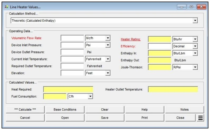
| Parameter | Description |
|---|---|
| Calculation Method | Specifies which method is used to perform the calculation: Theoretic (Calculated Enthalpy), Theoretic (Entered Enthalpy), or Theoretic (Entered Specific Heat). |
| Volumetric Flow Rate | Specifies or displays the maximum flow rate through the heater (standard volume units, adjusted to base conditions). Can be designated as the unknown. |
| Device Inlet Pressure | Specifies the gas pressure at the regulator (device) inlet, in gauge pressure. |
| Device Outlet Pressure | Specifies the gas pressure at the regulator (device) outlet, in gauge pressure. |
| Current Inlet Temperature | Specifies the current gas temperature at the regulator inlet before heating. |
| Required Outlet Temperature | Specifies the minimum required gas temperature at the regulator outlet (typically the hydrate formation temperature). |
| Elevation | Specifies the height above mean sea level at the heater location. Displayed when the Atmospheric Pressure Method is not set to “None” or “None – Entered Value.” |
| Heater Rating | Specifies or displays the heater rating (Btu/hr or kW). Can be designated as the unknown to solve for the required heater size. |
| Efficiency | Specifies or displays the thermodynamic efficiency of the line heater. Can be designated as the unknown. Represents the fraction of rated output actually transferred to the gas. |
| Enthalpy In | Specifies the enthalpy of the gas at the regulator inlet (Btu/lbm). Used with enthalpy-based calculation methods only. |
| Enthalpy Out | Specifies the enthalpy of the gas at the regulator outlet at hydrate formation conditions (Btu/lbm). Used with enthalpy-based methods only. |
| Joule-Thomson | Specifies the Joule-Thomson coefficient for the natural gas. Used with enthalpy and specific heat calculation methods. |
| Specific Heat | Specifies the constant-pressure specific heat (Cp) of the gas entering the regulator. Used with the Theoretic (Entered Specific Heat) method only. |
| Atm Pressure | Specifies the atmospheric pressure at the heater location. Displayed only when the Atmospheric Pressure Method is set to “None – Entered Value.” |
Part 2: Outputs/Reports
- u003cliu003eReview the Calculated Values section for Heat Required, Fuel Consumption, and Heater Outlet Temperature.u003c/liu003eu003cliu003eIf results are not as expected, adjust an input value and click Calculate again to iterate.u003c/liu003eu003cliu003eTo compare scenarios, use Additional Actions → Open Duplicate Calculation to open a copy with the current inputs and change one variable at a time.u003c/liu003eu003cliu003eTo SAVE the current calculation, click the Save command button. Saved files use the .htr extension.u003c/liu003eu003cliu003eTo open a previously saved calculation, click the Open command button.u003c/liu003eu003cliu003eTo PRINT, click the Print command button to access Print Settings. The report includes all input values and calculated results.u003c/liu003eu003cliu003eTo close without saving, click Cancel.u003c/liu003e
Results
| Output | Description |
|---|---|
| Volumetric Flow Rate | Specifies or displays the maximum flow rate through the heater (standard volume units, adjusted to base conditions). Can be designated as the unknown. |
| Heater Rating | Specifies or displays the heater rating (Btu/hr or kW). Can be designated as the unknown to solve for the required heater size. |
| Efficiency | Specifies or displays the thermodynamic efficiency of the line heater. Can be designated as the unknown. Represents the fraction of rated output actually transferred to the gas. |
| Heat Required | The calculated energy requirement — the amount of heat the heater must transfer to the gas to raise it from the Current Inlet Temperature to the Required Outlet Temperature (Btu/hr or kW). |
| Fuel Consumption | The calculated volume of pipeline gas consumed by the heater to deliver the required heat rate (cfh or m³/h). |
| Heater Outlet Temperature | The calculated temperature of the gas leaving the outlet side of the line heater and entering the downstream device (°F or °C). |
Notes & Considerations
- All pressure values displayed or entered on this screen are in gauge pressure. Internally, absolute pressure values are used in all calculations.
- The Volumetric Flow Rate is in standard volume units, adjusted to the base pressure and temperature specified in Base Conditions.
- The calculator assumes the gas flows through a pressure-reducing device (such as a regulator) immediately downstream of the heater. Device inlet pressure is the pressure just upstream of the device; device outlet pressure is just downstream.
- The Specific Heat value used in calculations represents heat capacity at constant pressure (Cp), not at constant volume.
- The Efficiency value represents the overall heat transfer efficiency of the heater — for example, if a heater rated at 100 MBtu/hr transfers only 80 MBtu/hr to the gas stream, the efficiency is 0.80 (80%).
- Enthalpy and Joule-Thomson values required for the enthalpy-based methods can be computed using GASCalc’s Thermodynamic Properties calculation routine.
- Red labels identify which items can be designated as the unknown. Click the label until it is underlined to select it. Only one item may be underlined (unknown) at a time.
- The Line Heater calculation is intended for preliminary sizing purposes. For detailed design and operating performance, consult the heater manufacturer.
References
- GASCalc™ 6.1 Calculation Reference: Line Heater Values, Revision 005, Copyright 2025
- American Gas Association — Measurement, GEOP Series Book M-1, 1993
- American Gas Association — Report No. 10, “Speed of Sound In Natural Gas and Other Related Hydrocarbon Gases,” 2003
- Van Wylen, Gordon J. and Sonntag, Richard E. — Fundamentals of Classical Thermodynamics, 2nd Edition, Revised Printing, 1978
- Holman, J.P. — Heat Transfer, 4th Edition, 1976
FAQ
-
What type of station does the Regulator & Monitor System calculator model?
The calculator models a two-stage (monitor-style) regulator and relief valve station in which gas pressure is reduced sequentially across two independent regulator stages. Each stage has its own relief valve and vent stack. This configuration is commonly used when codes require automatic overpressure protection at both stages of pressure reduction.
-
Which regulatory codes does this calculator support for compliance checks?
The calculator supports two regulatory codes for compliance checks: US DOT 49 CFR Part 192 (2019 edition) and ASME B31.8 (2007 edition). When a code is selected, the calculator compares the maximum calculated pressure in each piping section against the user-specified MAOP for that section using the allowable limits defined by that code. Results that exceed the allowable limits are highlighted in red on the Compliance data tab.
You can also select “None” to perform the hydraulic and flow calculations without any code-based compliance checking.
-
What information do I need before running this calculator?
Before running the calculator, you will need the following for each stage of the station:
For the supply piping, you need the minimum and maximum inlet pressures, the flowing gas temperature, the pipe and fitting specifications (size, wall thickness, length), and the pipe flow equation and efficiency. For each regulator, you need to select the manufacturer and model from the device database and enter the set pressure. For each relief valve, you need to select the model, enter the set pressure, minimum build-up pressure, and number of installed valves. For the vent stacks, you need the pipe and fitting specifications and whether the outlet discharges to atmosphere.
You will also need the gas composition or a gas properties file, base conditions (pressure and temperature), the minimum and maximum outlet flow rates, and — if performing compliance checks — the MAOP for each of the five piping sections: Upstream (Supply 1), Intermediate 1, Upstream (Supply 2), Intermediate 2, and Outlet.
-
What operating modes does the calculator support, and when should I use each one?
The calculator supports six operating modes, each representing a different assumption about which regulators are operating normally and which have failed.
Use Failed Upstream or Failed Downstream when you want to evaluate a single regulator failure while the other stage operates normally — these are the most common code-required failure scenarios. Use Failed Single to evaluate each regulator failing independently in two separate analyses. Use Failed Double to evaluate simultaneous failure of both regulators, which is the most conservative failure case. Use Normal to verify pressures and velocities under steady-state operation, and Normal Maximum to calculate the maximum flow capacity the combined station can deliver.
-
How does the calculator determine the inlet pressure to the second-stage supply piping?
The inlet pressure to the second-stage supply piping is not a direct user input — it is calculated internally based on the selected operating mode.
In most failure modes (Failed Single, Failed Double, Failed Downstream, Normal, and Normal Maximum), the second-stage inlet pressure is set equal to the first-stage regulator set pressure minus the pressure drop across the first-stage intermediate piping. In the Failed Upstream mode, however, the second-stage inlet pressure is instead set to the calculated build-up pressure at the outlet of the first-stage intermediate piping. This build-up pressure may be higher than the set pressure, since the first-stage relief valve is actively venting and the intermediate piping is operating under overpressure conditions. This distinction is important for correctly sizing the second-stage components in a failed upstream scenario.
-
What does the Relief Branch – First fitting do, and when should I use it?
In most physical installations, the relief valve is not installed inline with the intermediate piping — it is connected via a branch tee. This means the piping upstream of the tee carries both the relief valve flow and any downstream system flow, while the branch piping leading to the relief valve carries only the relief valve flow.
The Relief Branch – First component is a special fitting you add to the intermediate piping component list to tell the calculator where this branch point occurs. The calculator automatically splits the flow at that point: combined flow upstream of the component, relief-valve-only flow downstream. A Relief Branch – Second component is also available for installations with multiple identical relief valves sharing a common header, and is used to mark the point where the header splits to each individual valve.
-
What does the Operating Status field on the Relief Valve data tab mean?
The Operating Status field shows how the relief valve is responding under the calculated conditions. A status of Popping means the inlet pressure has reached or exceeded the relief valve set pressure and the valve is actively venting gas through the vent stack. A status of Continuously Closed means the inlet pressure is below the set pressure and the valve remains shut — no flow passes through the stack piping under those conditions.
In a failure scenario, you want to see Popping on the stage whose regulator has failed, which confirms the relief valve has opened and is handling the failed-regulator flow. If the relief valve is Continuously Closed when it should be venting, the relief valve may be undersized or the set pressure may be too high relative to the build-up pressure.
-
Is the 75% SMYS limit from DOT 192 §192.201(a)(2)(i) checked automatically?
No. When using the US DOT Part 192 regulatory code, the calculator performs MAOP-based compliance checks for each piping section, but it does not automatically evaluate the 75% SMYS hoop stress limit associated with §192.201(a)(2)(i).
If your calculated failed pressures are approaching the MAOP of any section — particularly on higher-pressure upstream piping — you should independently verify the resulting hoop stress using the Hoop Stress calculation routine in the Design & Stress Analysis module to confirm compliance with that limit.