
Introduction
The Rotary Meter Values calculator determines the volumetric flow rate through a rotary positive displacement meter, or calculates the required inlet pressure for a target flow rate, under specified operating conditions. The calculator applies a pressure-based capacity adjustment that corrects the meter’s published rated capacity to actual field conditions, accounting for operating pressure, temperature, gas specific gravity, compressibility factor, and base conditions. There is no consensus standard for sizing rotary meters — the calculator implements a single derived method based on empirical industry references. Results should ALWAYS be evaluated alongside the specific meter manufacturer’s documentation, particularly regarding rotor speed limits.
Background
Pressure and Capacity
Rotary meters are a type of positive displacement (PD) meter, a category that also includes diaphragm meters. Positive displacement devices measure gas flow by repeatedly filling and emptying a chamber of known, fixed volume. Each fill-and-empty cycle represents a discrete, measurable quantity of gas at the prevailing pressure and temperature. By counting these cycles, the meter accumulates a running total of the volume passed through it.
Manufacturers rate rotary meters at a specific inlet pressure. For example, a meter might carry a nameplate rating of 11,000 cfh at an inlet pressure of 0.25 inches W.C. It has long been industry practice to operate rotary meters at pressures other than their rated conditions — particularly at higher pressures — to handle larger flow applications with a smaller, less expensive meter body.
Because gas is compressible, the mass of gas contained in the meter’s reference chamber varies with pressure. Increasing the chamber pressure increases the number of standard volumes of gas the chamber holds at each cycle, which in turn increases the number of standard volumes the meter can measure per unit time. The fundamental relationship between pressure and volumetric flow rate is therefore the primary lever for adjusting a rotary meter’s effective capacity beyond its nameplate rating.
Meter sizing equations use this pressure-volume relationship to convert between the meter’s rated conditions and the actual operating conditions. The rated capacity is first corrected to the specified base pressure and temperature, then further corrected for the actual flowing pressure, temperature, specific gravity, and compressibility factor.
Meter Speed and Physical Limits
Increasing the differential pressure across the meter increases the rotational speed of the impellers. While higher speed increases the volumetric throughput, each rotary meter has a manufacturer-specified maximum speed. Exceeding this limit is likely to cause immediate or premature mechanical failure. Technical Toolboxes does not predict rotor speed and does not enforce speed-limit constraints — operators must consult the manufacturer’s documentation to confirm that the calculated operating point does not exceed the meter’s physical limits.
When sizing a rotary meter for a service, consideration should also be given to diversity of the downstream load. Where many gas-using appliances or pieces of equipment are present, the total connected load is typically derated by a coincidence or diversity factor to arrive at the design flow rate used for meter sizing.
Equations
Generic Rotary Meter Flow
The flow rate at flowing (metered) conditions is calculated in two steps. First, the meter’s rated capacity is converted to the specified base conditions:
Q_R = Q_{RATED} \times \left[\frac{P_{BR}}{P_B}\right] \times \left[\frac{T_B}{T_{BR}}\right] \times \left[\frac{Z_B}{Z_{BR}}\right]Q_R = Q_{RATED} \times \left[\frac{P_{BR}}{P_B}\right] \times \left[\frac{T_B}{T_{BR}}\right] \times \left[\frac{Z_B}{Z_{BR}}\right]
This base-corrected capacity is then adjusted to the actual flowing conditions:
Q_F = Q_R \times \left[\frac{P_F}{P_R}\right] \times \left[\frac{SG_R}{SG}\right]^{0.5} \times \left[\frac{T_R}{T_F}\right]^{0.5} \times \left[\frac{Z_R}{Z_F}\right]^{0.5}Q_F = Q_R \times \left[\frac{P_F}{P_R}\right] \times \left[\frac{SG_R}{SG}\right]^{0.5} \times \left[\frac{T_R}{T_F}\right]^{0.5} \times \left[\frac{Z_R}{Z_F}\right]^{0.5}
Where:
QF − Meter capacity at flowing (metered) conditions, ft3
QR − Meter capacity at rated conditions converted to specified base pressure and temperature, ft3
QRATED − Meter capacity at rated base pressure and temperature, ft3
PB − Base pressure, psia
PBR − Base pressure at rated conditions, psia
PF − Pressure at flowing (metered) conditions, psia
PR − Pressure at rated conditions, psia
SG − Specific gravity of flowing (metered) gas
SGR − Specific gravity at rated conditions
TB − Base temperature, °R
TBR − Base temperature at rated conditions, °R
TF − Temperature at flowing (metered) conditions, °R
TR − Temperature at rated conditions, °R [Assumed to be 60 °F/ 519.67 °R]
ZB − Compressibility factor at specified base conditions
ZBR − Compressibility factor at rated base conditions [Assumed to be 1.0]
ZF − Compressibility factor at flowing (metered) conditions
ZR − Compressibility factor at rated conditions
Absolute pressures are derived from gauge readings as follows:
PF = PFG + PATM
PR = PRG + PR_ATM
Where PFG and PRG are gauge pressures (psig) and PATM, PR_ATM are the respective atmospheric pressures (psia). Atmospheric pressure may be entered directly or calculated from elevation using the AGA method, as configured in Base Conditions.
Rated Capacity Adjustment Factor
The Rated Capacity Adjustment Factor expresses the ratio of the actual flowing capacity to the meter’s nameplate rated capacity:
FACTOR = \frac{Q_F}{Q_{RATED}}FACTOR = \frac{Q_F}{Q_{RATED}}
Where:
FACTOR − Rated Capacity Adjustment Factor, dimensionless
QF − Meter capacity at flowing (metered) conditions, ft3
QRATED − Meter capacity at rated base pressure and temperature, ft3
A factor greater than 1.0 indicates the meter can pass more standard volume flow than its nameplate capacity under the given operating conditions. The factor incorporates adjustments for operating pressure, temperature, differential, specific gravity, compressibility factor, atmospheric pressure, and base conditions.
Case Guide
Part 1: Create Case
- Select the Rotary Meter application from the Meters Module
- Click the Clear button to reset all values to blank (null)
- Click the Base Conditions button. Enter the base pressure and temperature, select a Gas Properties File or enter properties manually, select the Atmospheric Pressure Method, and optionally select a Compressibility Factor Method. Click Apply to save and return.
- From the Calculation Method list, select Generic Rotary Meter Flow
- In the Meter Data section, click the red label of the item to be solved (Flow Rate or Inlet Pressure) until the label is underlined — this identifies the unknown to be calculated
- Select the desired dimensional units for each data item
- Enter values for all known items: Meter Size/Type (use the ? button to browse the meter table), Inlet Pressure or Flow Rate, Elevation, and Flowing Temperature
- Click the Calculate button to compute the unknown value and the Rated Capacity Adjustment Factor
Input Parameters
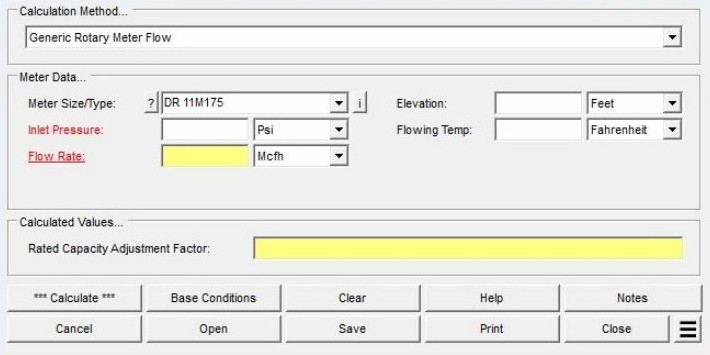
| Parameter | Description | Notes |
|---|---|---|
| Calculation Method | Selects which method is used to perform the calculation. Currently one method is available: Generic Rotary Meter Flow. | Required |
| Meter Size/Type | The manufacturer size/type code for the rotary meter. Capacity and rated-condition data are read automatically from the Meter Property Table when a meter is selected. | Use the ? button to browse available meters; click i to view the full property table for the selected meter |
| Inlet Pressure | Gauge pressure at the inlet (upstream) side of the meter. | Red label — may be selected as the unknown to solve for |
| Flow Rate | Volumetric flow rate through the meter at the specified conditions. | Red label — may be selected as the unknown to solve for |
| Flowing Temp | Temperature of the gas at flowing (metered) conditions. | Required |
| Elevation | Height above mean sea level at the meter location, used to calculate atmospheric pressure. | Displayed only when Atmospheric Pressure Method in Base Conditions is not set to “None” or “None – Entered Value” |
| Atm Pressure | Atmospheric pressure at the meter location, entered directly by the user. | Displayed only when Atmospheric Pressure Method in Base Conditions is set to “None – Entered Value” |
| Compressibility Factor (Base) | Compressibility factor (Z) for the gas at the specified base conditions, entered manually. | Displayed only when Compressibility Factor Method in Base Conditions is set to “None – Entered Values” |
| Compressibility Factor (Flowing) | Compressibility factor (Z) for the gas at flowing (metered) conditions, entered manually. | Displayed only when Compressibility Factor Method in Base Conditions is set to “None – Entered Values” |
Part 2: Outputs/Reports
- If you need to modify an input, update the value and click Calculate again to refresh the results.
- To save the calculation, click the Save button. The file is saved as a .rtm file that can be reopened later with the Open button.
- To print the inputs and results, click the Print button to open the Print Settings screen.
- To calculate results across a range of input values, select Calculate Table of Results from the Additional Actions menu.
- To compare two scenarios side-by-side, select Open Duplicate Calculation from the Additional Actions menu. This opens a second screen pre-loaded with the current values.
- Click Close to save and exit the screen, or Cancel to exit without saving.
Results
| Output | Description | Notes |
|---|---|---|
| Flow Rate | Calculated volumetric flow rate through the meter at the specified operating conditions. | Displayed when Flow Rate is selected as the unknown (underlined label) |
| Inlet Pressure | Calculated gauge pressure required at the upstream side of the meter to achieve the specified flow rate. | Displayed when Inlet Pressure is selected as the unknown (underlined label) |
| Rated Capacity Adjustment Factor | Dimensionless multiplier that converts the meter’s nameplate rated capacity to its actual capacity at the specified operating conditions. Accounts for differences in pressure, temperature, specific gravity, compressibility factor, atmospheric pressure, and base conditions relative to the manufacturer’s rated conditions. A value greater than 1.0 indicates the meter can pass more flow than its nameplate rating at the given conditions. | Always calculated |
References
- American Gas Association — Measurement, GEOP Series Book M-1, 1993.
- DMD Dresser — The Application of Temperature and/or Pressure Correction Factors in Gas Measurement, RM 135, 1999.
FAQ
-
What information do I need before running a meter calculation?
You will need the meter size/type code (selectable from the built-in meter table), the known value for either inlet pressure or flow rate, the flowing temperature, elevation or atmospheric pressure at the meter location, and base conditions including base pressure and temperature. Gas properties — particularly specific gravity — are also required, either entered manually or loaded from a gas properties file. If compressibility corrections are needed, a compressibility factor method must also be selected in Base Conditions.
-
What is the Rated Capacity Adjustment Factor and how should I interpret it?The Rated Capacity Adjustment Factor is the ratio of the meter’s actual flowing capacity (at the specified operating conditions) to its nameplate rated capacity. A factor greater than 1.0 indicates the meter can handle more standard volume flow than its nameplate rating under the given conditions — typically because the operating pressure is higher than the rated pressure. The factor is useful for confirming that a given meter size can handle the required flow at the intended operating pressure
-
Are there any limitations or assumptions in the calculation I should be aware of?Yes. GASCalc assumes the compressibility factor at rated base conditions (Z_BR) equals 1.0 and that the rated temperature (T_R) is 60 °F. The calculator does not predict rotor speed or enforce manufacturer speed limits — exceeding the meter’s maximum rated speed can cause immediate or premature mechanical failure, so results must be checked against the manufacturer’s specifications. Additionally, there is no common consensus standard for meter sizing, so this method may differ from the approach used by a specific meter manufacturer.
-
When should I use the Meter Values calculator versus the Meter MatchMaker?Use the Meter MatchMaker when you have not yet selected a meter and need to identify which size and type best fits a given application. Once a specific meter model has been chosen, use that meter’s Values calculator to confirm or compute the flow rate or inlet pressure at defined operating conditions and to determine the Rated Capacity Adjustment Factor.