
This application calculates the flow and pressure values for a relief valve operating as part of an integrated system that includes upstream supply piping and downstream vent stack piping. The calculator models all three sections together — upstream piping, relief valve, and vent stack — iterating until the system flow balances the overall pressure drop. Compliance data is also evaluated to verify capacity and build-up pressure against user-specified requirements.
Note: The model assumes nominal operation of the fully opened relief valve. It does not model the internal sense, control, or valve-opening behavior. To calculate relief valve performance without the associated piping, use the Relief Valve Values calculator instead.
Background
Evaluating a relief valve in isolation gives only a partial picture of its adequacy. The upstream piping connecting the valve to the protected system must have sufficient capacity to convey the gas to be vented, and the downstream vent stack must be able to discharge that gas without restricting the valve’s performance. Pressure losses in either section increase the build-up pressure on the protected system — potentially beyond acceptable limits.
Flow rates through relief valve systems are typically very large and often approach sonic velocity. When a pipe segment reaches sonic flow it becomes “choked” — the flow cannot increase further without an increase in upstream pressure. Choked flow in a vent stack raises back pressure on the relief valve, reduces the valve’s capacity, and drives up build-up pressure on the protected system. Industry standards generally recommend that pressure loss across the inlet piping not exceed 3 percent of the set pressure, and that pressure loss across the vent stack not exceed 10 percent. Where those limits cannot be met, it is critical at minimum to maintain sub-sonic velocities and keep piping losses at a level that does not render the valve’s performance inadequate.
When sonic flow does occur in the vent stack, the calculator assumes that the stack is choked at its outlet end and calculates the outlet pressure as the maximum value that still allows sonic flow. Under these conditions the calculated stack outlet pressure may exceed the atmospheric pressure or the user-specified outlet pressure.
Field comparison studies indicate that common industry pipe flow equations yield optimistic flow rates for flowing vent stacks. Correlation between predicted and field results is strongest when the Colebrook pipe flow equation is used with a pipe/hydraulic efficiency of 0.5 and the Limit Pipe Velocity To Sonic preference option is selected. These settings are recommended for vent stack piping.
Calculation Method
The Relief Valve & Piping System calculator does not use a single closed-form equation. Instead, it combines the methods from two other routines:
The upstream piping components are collapsed into a single equivalent segment and the vent stack components are collapsed into one or more equivalent segments (depending on the number of valves). Pipe and fitting flow is calculated using the same methods as the Pipe Flow calculator. Relief valve flow is calculated using the same methods as the Relief Valve Values calculator.
Using an iterative process, the flow rate through the system is computed and the pressure difference across the entire system — upstream piping, relief valve, and vent stack — is compared to the known boundary pressures. Iteration continues until the system flow produces the correct overall pressure drop. At convergence, build-up pressure, vent stack back pressure, compliance status, and all velocity values are reported.
Relief branch components
When the relief valve taps off a main supply line (rather than terminating the line), a Relief Branch — First fitting component is added to the upstream piping list to mark the branch point. Flow upstream of that fitting equals relief valve flow plus any downstream system flow; flow between the branch and the valve equals relief valve flow only.
When multiple identical relief valves are installed, a Relief Branch — Second fitting marks where the common run splits to each individual valve. Flow upstream of the First branch equals total relief flow plus downstream flow; flow between First and Second branches equals total relief flow; flow from the Second branch to each valve equals single-valve flow.
Example Calculation
Calculate the maximum flow rate for a Generic API 520 rated 2-inch × 3-inch relief valve with a “G” orifice in the following system:
| Parameter | Value (US Customary) | Value (SI) |
|---|---|---|
| Upstream pipe | 2-inch standard wall steel, 5 Feet | 2-inch standard wall steel, 1.5 Metres |
| Upstream fitting | (1) 2-inch V-Ball valve | (1) 2-inch V-Ball valve |
| Upstream pipe efficiency | 0.95 | 0.95 |
| Upstream pipe flow equation | IGT-Improved | IGT-Improved |
| Inlet Pressure | 110 Psig | 7585 Millibar |
| Elevation | 0 Feet | 0 Metres |
| Flowing Temperature | 60°F | 15°C |
| Relief valve model | Generic API 520, 2×3, Orifice G | Generic API 520, 2×3, Orifice G |
| Set Pressure | 100 Psig | 6895 Millibar |
| Minimum Build-Up Pressure | 0 Psig | 0 Millibar |
| Number of Valves | 1 | 1 |
| Downstream Flow Rate | 0 Mcfh | 0 m³/h |
| Stack pipe | 3-inch standard wall steel, 6 Feet | 3-inch standard wall steel, 2 Metres |
| Stack fitting | (1) 3-inch Pipe Exit | (1) 3-inch Pipe Exit |
| Stack pipe efficiency | 0.5 | 0.5 |
| Stack pipe flow equation | Colebrook | Colebrook |
| Required relief capacity | 30 Mcfh | 850 m³/h |
| Allowable Build-Up Pressure | 110 Psig | 7585 Millibar |
| Velocity Limit | Sonic | Sonic |
| Base Pressure | 14.73 Psia | 1013.25 Millibar |
| Base Temperature | 60°F | 15°C |
| Atmospheric Pressure Method | AGA | AGA |
Results:
| Section | Value (US) | Value (SI) |
|---|---|---|
| Upstream — Flow Rate | 82 Mcfh | 2337 m³/h |
| Upstream — Outlet Pressure | 109.71 Psi | 7565.05 Millibar |
| Upstream — Maximum Velocity | 116.3 Feet/sec | 35.4 Metres/sec |
| Relief Valve — Inlet (Build-Up) Pressure | 109.71 Psi | 7565.05 Millibar |
| Relief Valve — Outlet (Back) Pressure | 4.14 Psi | 292.10 Millibar |
| Relief Valve — Outlet Temperature | 57.0°F | 13.3°C |
| Relief Valve — Flow Rate | 82 Mcfh | 2337 m³/h |
| Relief Valve — Sizing Factor | 0.503 in² | 3.245 cm² |
| Relief Valve — Outlet Velocity | 346.2 Feet/sec | 104.8 Metres/sec |
| Relief Valve — Operating Status | Continuously Open | Continuously Open |
| Stack — Inlet Pressure | 4.14 Psi | 292.10 Millibar |
| Stack — Outlet Pressure | 0.00 Psi | 0.00 Millibar |
| Stack — Maximum Velocity | 443.4 Feet/sec | 135.0 Metres/sec |
| Compliance — Calculated Capacity | 82 Mcfh | 2337 m³/h |
| Compliance — Calculated Build-Up Pressure | 109.71 Psi | 7565.05 Millibar |
| Compliance — Allowable Maximum Velocity | 1390.4 Feet/sec | 423.4 Metres/sec |
| Compliance — Calculated Maximum Velocity | 443.4 Feet/sec | 135.0 Metres/sec |
Case Guide
Part 1: Create Case
- Select the Relief Valve & Piping System application from the Valves & Fittings Module.
- Click Clear to reset all values, then click Base Conditions. Set base pressure, base temperature, gas properties file, and atmospheric pressure method. Click Apply.
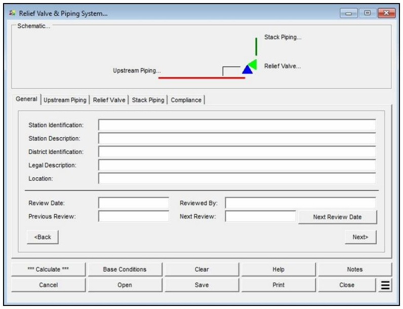
- On the General tab, optionally enter Station ID, description, location, review dates, and reviewer information (not required for calculation).
- On the Upstream Piping tab, click Add to build the components list — add pipe segments and fittings in order from inlet to relief valve. Set Pipe Efficiency, Pipe Flow Equation, Inlet Pressure, Elevation, and Flowing Temperature. Click the red Flow Rate label until underlined to designate it as the unknown.
- On the Relief Valve tab, click the ? button next to Size/Type to select the valve from the Device Selection screen. Enter Set Pressure, Minimum Build-Up Pressure, Number of Valves, and Downstream Flow Rate.
- On the Stack Piping tab, click Add to build the vent stack components list — add pipe segments and fittings in order from relief valve to atmosphere. Include a Pipe Exit fitting as the final component. Set Pipe Efficiency and Pipe Flow Equation. Select Set To Atmospheric Pressure for the outlet, or enter a specific outlet pressure.
- On the Compliance tab, enter Required Relief Valve & Stack Capacity, Allowable Build-Up Pressure, and Velocity Limit.
- Return to the Upstream Piping tab and click Calculate.
Input Parameters
| Parameter | Description |
|---|---|
| General — Station Identification | Optional. Specifies the installation identification for documentation purposes. |
| General — Station Description | Optional. Specifies the installation description. |
| General — District Identification | Optional. Specifies the district identification for the installation. |
| General — Legal Description | Optional. Specifies the legal description of the installation site. |
| General — Location | Optional. Specifies the physical location of the installation. |
| General — Review Date / Reviewed By / Previous & Next Review | Optional documentation fields for periodic inspection records (format MM/DD/YYYY). The Next Review Date button calculates the next required review date based on the selected regulatory code. |
| Upstream Piping — Components | List of pipe segments and fittings between the supply system and the relief valve inlet. Must contain at least one component. Use Add, Insert, Delete, and Clear to manage the list. |
| Upstream Piping — Inlet Pressure | Gauge pressure at the inlet (upstream) end of the upstream piping (Psi or Millibar). Can be set as the unknown. |
| Upstream Piping — Flow Rate | Flow rate through the upstream piping (Mcfh or m³/h). Can be set as the unknown. |
| Upstream Piping — Flowing Temperature | Temperature of the gas at the inlet to the upstream piping (Fahrenheit or Celsius). |
| Upstream Piping — Elevation | Height above mean sea level at the installation. Displayed when Atmospheric Pressure Method is not set to “None” or “None — Entered Value.” |
| Upstream Piping — Atm Pressure | Atmospheric pressure at the location (psia). Displayed only when Atmospheric Pressure Method is set to “None — Entered Value.” |
| Upstream Piping — Pipe Efficiency | Hydraulic efficiency of the upstream piping components (decimal, 0–1). |
| Upstream Piping — Pipe Flow Equation | The pipe flow equation applied to the upstream piping (e.g., IGT-Improved, Colebrook). |
| Relief Valve — Size/Type | The relief valve Size/Type Code. Click the ? button to select a device from the Device Selection screen. Selecting a device auto-populates the Sizing Factor. |
| Relief Valve — Set Pressure | The pressure at which the relief valve opens (psig or Millibar). Assumed to be sensed immediately upstream of the valve. |
| Relief Valve — Minimum Build-Up Pressure | The minimum additional pressure above set pressure required to fully open the relief valve. Enter the manufacturer’s value, or 0 if unknown. |
| Relief Valve — Number of Valves | The number of identical relief valve and vent stack combinations installed. Each valve and stack is assumed to be identical in size, type, and configuration. |
| Relief Valve — Downstream Flow Rate | The system flow downstream of the relief valve that does not pass through the vent stack (Mcfh or m³/h). Enter 0 if no downstream demand exists. |
| Stack Piping — Components | List of pipe segments and fittings in the vent stack downstream of the relief valve. Must contain at least one component. Include a Pipe Exit fitting as the final item. |
| Stack Piping — Pipe Efficiency | Hydraulic efficiency of the vent stack piping (decimal, 0–1). A value of 0.5 is recommended based on field correlation studies. |
| Stack Piping — Pipe Flow Equation | The pipe flow equation applied to the vent stack (Colebrook recommended). |
| Stack Piping — Set To Atmospheric Pressure | When selected, the stack outlet pressure is set equal to local atmospheric pressure and the Outlet Pressure field is disabled. |
| Stack Piping — Outlet Pressure | Gauge pressure at the outlet (downstream) end of the vent stack (psig or Millibar). Enabled only when Set To Atmospheric Pressure is not selected. |
| Compliance — Required Relief Valve & Stack Capacity | The minimum required venting capacity to meet design or regulatory requirements (Mcfh or m³/h). |
| Compliance — Allowable Build-Up Pressure | The maximum allowable build-up pressure at the inlet of the relief valve (psig or Millibar). |
| Compliance — Velocity Limit | Specifies how the maximum allowable velocity is set: from Preferences, Sonic, or a manually entered value. |
Part 2: Outputs/Reports
- After calculating, review each data tab — flashing tab headings indicate a velocity or compliance limit has been exceeded.
- To modify any input, make the change and click Calculate again.
- To SAVE, click the Save button. The file is saved with a .rss extension.
- To generate a REPORT, click Print. Three output formats are available: Standard (full data and schematic), Short Report (schematic with abbreviated data, relief valve results, and compliance summary), and Inspection Form (limited data with a field inspection checklist).
- To compare scenarios, use Additional Actions → Open Duplicate Calculation to open a copy of the current values in a new screen.
Results
| Output | Description |
|---|---|
| Upstream — Outlet Pressure | Calculated gauge pressure at the outlet (downstream) end of the upstream piping — this is also the inlet (build-up) pressure to the relief valve (psig or Millibar). |
| Upstream — Maximum Velocity | Calculated maximum gas velocity through the upstream piping, based on the smallest inside diameter of the assigned components (Feet/sec or Metres/sec). |
| Relief Valve — Sizing Factor | Displays the rated sizing factor or orifice area for the selected relief valve. Auto-populated when a valve is selected from the Size/Type list (in², cm², or dimensionless valve factor depending on valve type). |
| Relief Valve — Inlet (Build-Up) Pressure | Calculated pressure at the inlet (upstream) side of the relief valve — equal to the system build-up pressure (psig or Millibar). |
| Relief Valve — Outlet (Back) Pressure | Calculated pressure at the outlet (downstream) side of the relief valve — equal to the back pressure imposed by the vent stack (psig or Millibar). |
| Relief Valve — Outlet Temperature | Estimated gas temperature at the outlet of the relief valve, calculated using the Joule-Thomson method (°F or °C). Valid only for high-methane-content gases. |
| Relief Valve — Flow Rate | Calculated flow rate through the relief valve at the computed system conditions (Mcfh or m³/h). |
| Relief Valve — Outlet Velocity | Calculated gas velocity at the outlet of the relief valve, based on flow rate, outlet temperature, outlet pressure, and the valve’s listed outlet diameter (Feet/sec or Metres/sec). |
| Relief Valve — Operating Status | Displays the operating status of the relief valve (e.g., Continuously Open, Closed). |
| Stack — Inlet Pressure | Calculated pressure at the inlet (upstream) end of the vent stack piping (psig or Millibar). |
| Stack — Outlet Pressure | Calculated pressure at the outlet (downstream) end of the vent stack. Under sonic (choked) flow, this value may exceed the specified atmospheric or user-entered outlet pressure (psig or Millibar). |
| Stack — Flow Rate | Calculated flow rate through the vent stack piping (Mcfh or m³/h). |
| Stack — Maximum Velocity | Calculated maximum gas velocity through the vent stack, based on the smallest inside diameter of the assigned components (Feet/sec or Metres/sec). |
| Compliance — Relief Valve & Stack Capacity | Calculated total venting capacity of the relief valve and vent stack at the computed system conditions (Mcfh or m³/h). Compared to the Required capacity entered on the Compliance tab. |
| Compliance — Build-Up Pressure | Calculated build-up pressure at the inlet of the relief valve. Compared to the Allowable Build-Up Pressure entered on the Compliance tab (psig or Millibar). |
| Compliance — Maximum Velocity | The maximum computed velocity occurring anywhere in the relief valve, upstream piping, or stack piping. Compared to the Allowable Maximum Velocity (Feet/sec or Metres/sec). |
Notes
All pressure values entered or displayed in this calculator are gauge pressures. All flow values represent standard volumes adjusted to the base pressure and temperature specified in Base Conditions. Temperature change across the relief valve is calculated using the Joule-Thomson method, which is valid only for high-methane-content gases; this calculation can be suppressed in Preferences. No temperature change is calculated for pipe sections. Pipe and fitting diameters and roughness values are read from the Pipe Property Table and Fitting Property Table respectively. When the Flash Schematic Item and Flash Data Tab On Calculation/Compliance Error preference options are enabled, the schematic labels and data tab headings will highlight when associated data or limits are exceeded.
References
- GASCalc 6.1 — Pipe Flow Calculation Reference, Revision 004, Copyright 2025.
- GASCalc 6.1 — Relief Valve Values Calculation Reference, Revision 004, Copyright 2025.
- GASCalc 6.1 — Pipe Vent Time Calculation Reference, Revision 004, Copyright 2025.
- GASCalc 6.1 — Velocity Calculation Reference, Revision 004, Copyright 2025.
FAQ
-
What type of station does the Regulator & Monitor System calculator model?
The calculator models a two-stage (monitor-style) regulator and relief valve station in which gas pressure is reduced sequentially across two independent regulator stages. Each stage has its own relief valve and vent stack. This configuration is commonly used when codes require automatic overpressure protection at both stages of pressure reduction.
-
Which regulatory codes does this calculator support for compliance checks?
The calculator supports two regulatory codes for compliance checks: US DOT 49 CFR Part 192 (2019 edition) and ASME B31.8 (2007 edition). When a code is selected, the calculator compares the maximum calculated pressure in each piping section against the user-specified MAOP for that section using the allowable limits defined by that code. Results that exceed the allowable limits are highlighted in red on the Compliance data tab.
You can also select “None” to perform the hydraulic and flow calculations without any code-based compliance checking.
-
What information do I need before running this calculator?
Before running the calculator, you will need the following for each stage of the station:
For the supply piping, you need the minimum and maximum inlet pressures, the flowing gas temperature, the pipe and fitting specifications (size, wall thickness, length), and the pipe flow equation and efficiency. For each regulator, you need to select the manufacturer and model from the device database and enter the set pressure. For each relief valve, you need to select the model, enter the set pressure, minimum build-up pressure, and number of installed valves. For the vent stacks, you need the pipe and fitting specifications and whether the outlet discharges to atmosphere.
You will also need the gas composition or a gas properties file, base conditions (pressure and temperature), the minimum and maximum outlet flow rates, and — if performing compliance checks — the MAOP for each of the five piping sections: Upstream (Supply 1), Intermediate 1, Upstream (Supply 2), Intermediate 2, and Outlet.
-
What operating modes does the calculator support, and when should I use each one?
The calculator supports six operating modes, each representing a different assumption about which regulators are operating normally and which have failed.
Use Failed Upstream or Failed Downstream when you want to evaluate a single regulator failure while the other stage operates normally — these are the most common code-required failure scenarios. Use Failed Single to evaluate each regulator failing independently in two separate analyses. Use Failed Double to evaluate simultaneous failure of both regulators, which is the most conservative failure case. Use Normal to verify pressures and velocities under steady-state operation, and Normal Maximum to calculate the maximum flow capacity the combined station can deliver.
-
How does the calculator determine the inlet pressure to the second-stage supply piping?
The inlet pressure to the second-stage supply piping is not a direct user input — it is calculated internally based on the selected operating mode.
In most failure modes (Failed Single, Failed Double, Failed Downstream, Normal, and Normal Maximum), the second-stage inlet pressure is set equal to the first-stage regulator set pressure minus the pressure drop across the first-stage intermediate piping. In the Failed Upstream mode, however, the second-stage inlet pressure is instead set to the calculated build-up pressure at the outlet of the first-stage intermediate piping. This build-up pressure may be higher than the set pressure, since the first-stage relief valve is actively venting and the intermediate piping is operating under overpressure conditions. This distinction is important for correctly sizing the second-stage components in a failed upstream scenario.
-
What does the Relief Branch – First fitting do, and when should I use it?
In most physical installations, the relief valve is not installed inline with the intermediate piping — it is connected via a branch tee. This means the piping upstream of the tee carries both the relief valve flow and any downstream system flow, while the branch piping leading to the relief valve carries only the relief valve flow.
The Relief Branch – First component is a special fitting you add to the intermediate piping component list to tell the calculator where this branch point occurs. The calculator automatically splits the flow at that point: combined flow upstream of the component, relief-valve-only flow downstream. A Relief Branch – Second component is also available for installations with multiple identical relief valves sharing a common header, and is used to mark the point where the header splits to each individual valve.
-
What does the Operating Status field on the Relief Valve data tab mean?
The Operating Status field shows how the relief valve is responding under the calculated conditions. A status of Popping means the inlet pressure has reached or exceeded the relief valve set pressure and the valve is actively venting gas through the vent stack. A status of Continuously Closed means the inlet pressure is below the set pressure and the valve remains shut — no flow passes through the stack piping under those conditions.
In a failure scenario, you want to see Popping on the stage whose regulator has failed, which confirms the relief valve has opened and is handling the failed-regulator flow. If the relief valve is Continuously Closed when it should be venting, the relief valve may be undersized or the set pressure may be too high relative to the build-up pressure.
-
Is the 75% SMYS limit from DOT 192 §192.201(a)(2)(i) checked automatically?
No. When using the US DOT Part 192 regulatory code, the calculator performs MAOP-based compliance checks for each piping section, but it does not automatically evaluate the 75% SMYS hoop stress limit associated with §192.201(a)(2)(i).
If your calculated failed pressures are approaching the MAOP of any section — particularly on higher-pressure upstream piping — you should independently verify the resulting hoop stress using the Hoop Stress calculation routine in the Design & Stress Analysis module to confirm compliance with that limit.