
Introduction
This application calculates the time required to vent a single pipe segment or a group of pipe segments from an initial pressure to a specified final pressure through a vent connection. The vent connection can be composed of various pipe and fitting components, and the outlet pressure can be set to atmospheric or a user-specified value. It is strongly recommended to use the Colebrook pipe flow equation with a pipe efficiency of 0.5 and to enable the Limit Pipe Velocity To Sonic preference option when performing pipe vent calculations, as these settings have been validated against field results.
Background
When venting a pipe segment or group of pipe segments, the pressure inside the segment(s) decreases continuously as gas is released through the vent connection. At the start of venting, if the initial pressure is significantly higher than the outlet pressure, the flow velocity at the vent stack outlet may reach sonic (choked) conditions. During this sonic phase, the flow velocity remains approximately constant, but the volumetric flow rate through the vent connection decreases as the pressure in the segment(s) drops. Once the pressure differential falls below the threshold required to sustain sonic flow, both the velocity and volumetric flow rate decrease together until the specified final pressure is reached.
The Pipe Vent Time calculator uses a time-step algorithm to account for these varying pressure and flow conditions throughout the venting process. At each time step, the pressure within the vented segment(s) is assumed to be uniform throughout the entire volume — that is, the pressure at one end of the segment(s) equals the pressure at the opposite end. The flow rate through the vent connection is recomputed at each step based on the current pressure difference, and the change in pressure and volume is calculated before advancing to the next step. This process continues recursively until the specified final pressure is reached.
Sonic Flow at the Vent Stack Outlet
In typical discussions of pipe venting, it is assumed that the pressure at the outlet end of the vent stack equals atmospheric pressure. This is accurate under subsonic flow conditions. However, under sonic flow conditions, the pressure at the outlet end of the stack will exceed atmospheric pressure. The venting calculator accounts for this by assuming the vent stack is choked at its outlet when sonic conditions are present. In this case, the outlet pressure is set to the minimum value required to sustain sonic flow, rather than atmospheric pressure. As the pipe pressure decreases and subsonic conditions are eventually restored, the outlet pressure returns to atmospheric.
Hydraulic Efficiency Recommendation
The results of this venting calculator has been compared to actual field measurements and correlate well when appropriate parameters are selected. Field comparisons have shown that standard pipe flow equations tend to produce overly optimistic (high) flow rates under vent stack conditions. To match field results, hydraulic efficiency values on the order of 0.4 to 0.6 are required. Specifically, strong correlation between predicted and measured values was found when using the Colebrook pipe flow equation with a pipe efficiency of 0.5 and with the pipe velocity limited to sonic velocity. It is recommended to apply these settings for all pipe vent calculations.
Calculation Method
The Pipe Vent Time calculation combines equations from several other calculation routines into a unified method. There is no single governing equation; instead, the method operates as follows:
The flow through the vent connection is calculated using the same methods as in the Pipe Flow calculation routine. All vent components (pipe segments, fittings, valves, pipe exits) are combined into a single equivalent segment based on their associated equivalent length values. The pressure difference between the outlet pressure and the current pressure in the vented segment(s) is used to compute the flow rate through this equivalent vent segment. That flow rate is held constant for a short time step, during which gas is removed from the vented segment(s) and the pressure decreases. The method then recomputes the flow rate based on the updated pressure and continues stepping until the specified final pressure is reached.
When multiple pipe segments are included in the vented group, their individual volumes are combined into a total volume, and an equivalent diameter and length representing that total volume are used in the calculation. The various volume values (Initial Volume, Final Volume, Change In Volume) reported by the calculator represent standard volumes — that is, the gas volume adjusted to the base pressure and temperature specified in the Base Conditions settings. Volume computations follow the same approach used in the Pipe Volume calculation routine.
Using the Pipe Vent Time Calculator
Part 1: Create Case
- Select the Vent Time application from the Pipe Module. The Pipe Vent Time calculation screen will be displayed.
- Click the Clear command button to reset all values to blank (null).
- Click the Base Conditions command button. Enter the appropriate base pressure and temperature, select or configure a gas properties file, and choose an Atmospheric Pressure Method. Click Apply to return to the calculation screen.
- In the Pipe Data — Segments To Be Vented section, click Add to open the Piping Components screen. On the Piping data tab, select the pipe size/type and enter the length for each segment to be vented. Click Add after configuring each segment. At least one pipe-type component is required; fittings cannot be included in this list.
- In the Pipe Data — Vent Connection section, click Add to open the Piping Components screen. Add all vent connection components in sequence — vent pipe segments (Piping data tab), fittings and valves (Fittings data tab), and a pipe exit fitting. At least one component is required. When more than one vent stack is used, all stacks are assumed to be composed of identical components; set the Number Of Vents field accordingly.
- Set the Outlet Pressure: check the Atmospheric Pressure checkbox to vent to atmosphere (0 psig), or enter a specific outlet pressure value.
- Enter the Vent Efficiency value (recommended: 0.5) and select the Vent Equation (recommended: Colebrook).
- In the Conditions section, enter the Initial Pressure and set the Final Pressure: check the Atmospheric Pressure checkbox to vent to 0 psig, or enter a specific final pressure. Enter the Elevation (used to compute average atmospheric pressure when an AGA or elevation-based method is selected) and the average gas Temperature.
- Click on the red label for the item to be solved (the “unknown”) until it is underlined. Typically, Elapsed Time To Vent To Final Pressure is the unknown. Select the desired units for all data items.
- Click the Calculate command button.
Input Parameters
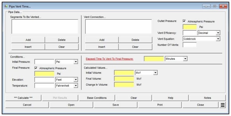
| Parameter | Description |
|---|---|
| Atm Pressure | Specifies the average atmospheric pressure for the pipe segment(s) and vent connection. Only displayed when the Atmospheric Pressure Method in Base Conditions is set to “None – Entered Value.” |
| Atmospheric Pressure (Final Pressure) | When selected, the final pressure in the pipe segment(s) is set to atmospheric pressure (0 psig) and the Final Pressure data field is disabled. |
| Atmospheric Pressure (Outlet Pressure) | When selected, the outlet pressure of the vent connection is set to atmospheric pressure (0 psig) and the Outlet Pressure data field is disabled. |
| Elapsed Time To Vent To Final Pressure | Specifies or displays the elapsed time required to vent the pipe segment(s) to the specified final pressure. This is the typical “unknown” value to be calculated. |
| Elevation | Specifies the average height above mean sea level for the pipe segment(s) and vent connection. Used to compute average atmospheric pressure. Only displayed when the Atmospheric Pressure Method is not set to “None” or “None – Entered Value.” |
| Final Pressure | Specifies or displays the final pressure of the segment(s) to be vented. Only enabled when the Atmospheric Pressure (Final Pressure) option is unselected. |
| Initial Pressure | Specifies the initial gauge pressure of the segment(s) to be vented. |
| Number Of Vents | Specifies the number of similar vent connections. When greater than one, all stacks are assumed to be composed of identical components. |
| Outlet Pressure | Specifies or displays the outlet pressure of the vent connection. Only enabled when the Atmospheric Pressure (Outlet Pressure) option is unselected. |
| Segments To Be Vented | Displays the pipe segments associated with the volume to be vented. Use the Add, Insert, Delete, and Clear command buttons to manage the list. At least one pipe-type segment is required; fitting-type components are not permitted in this list. |
| Temperature | Specifies the average temperature of the gas contained in the pipe segment(s). |
| Vent Connection | Displays the components associated with the vent connection piping (pipe segments, fittings, valves, and pipe exit). Use the Add, Insert, Delete, and Clear command buttons to manage the list. At least one component is required. |
| Vent Efficiency | Specifies the hydraulic efficiency value to be used when calculating flow through the vent connection components. Recommended value: 0.5. |
| Vent Equation | Specifies the pipe flow equation used to calculate flow through the vent connection components. Recommended setting: Colebrook. The unknown value should be recalculated if the method is changed. |
Part 2: Outputs/Reports
- After clicking Calculate, review the results in the Calculated Values section. The Elapsed Time To Vent To Final Pressure and volume values (Initial Volume, Final Volume, Change In Volume) will be displayed in the selected units.
- To view a plot of pipe pressure, vent rate, vent velocity, and outlet pressure over time, click the Plot Results command button (only enabled after a calculation has been performed).
- To modify an input parameter and recalculate, make the change and click Calculate again.
- To compare results by changing one or more values without re-entering all data, use the Open Duplicate Calculation Additional Action.
- To add a title or notes to the current calculation, click the Notes command button.
- To Save the calculation, click the Save command button. Calculation files use the .vnt extension.
- To print the data values and results, click the Print command button and configure the Print Settings screen.
Results
| Output | Description |
|---|---|
| Elapsed Time To Vent To Final Pressure | Displays the calculated elapsed time required to vent the pipe segment(s) from the initial pressure to the specified final pressure through the vent connection. Displayed in the selected time units (e.g., Minutes). |
| Initial Volume | Displays the calculated amount of gas contained in the pipe segment(s) at the initial pressure conditions, adjusted to the specified base pressure and temperature (standard volume). Units are user-selectable (e.g., Mcf, m3). |
| Final Volume | Displays the calculated amount of gas remaining in the pipe segment(s) at the final pressure conditions, adjusted to the specified base pressure and temperature (standard volume). |
| Change In Volume | Displays the calculated change in the amount of gas contained in the pipe segment(s) between the initial and final conditions, adjusted to the specified base pressure and temperature (standard volume). Represents the total gas released through the vent connection. |
| Plot Results (Calculation Results Plot) | Available via the Plot Results command button after a calculation is complete. Displays time-series plots of Pipe Pressure, Vent Rate, Vent Velocity, and Outlet Pressure across the Combination, Pipe Pressure, Vent Rate, Vent Velocity, and Outlet Pressure tabs. Time-step results are stored in a log file. |
Note: All pressure values in this calculator are gauge pressure values. Volume values represent standard volumes (adjusted to the base pressure and temperature specified in Base Conditions). To adjust the number of decimal places displayed for any calculated item, go to File > Preferences > Decimals. The Elevation value is used to compute average atmospheric pressure; it is only displayed when the Atmospheric Pressure Method is not “None” or “None – Entered Value.” The Limit Pipe Velocity To Sonic preference option (File > Preference Settings) must be enabled for results consistent with field-validated recommendations.
References
- American Society of Heating, Refrigerating and Air-Conditioning Engineers, Fundamentals, 2009 ASHRAE Handbook Inch Pound Edition.
- American Gas Association, Measurement, GEOP Series Book M-1, 1993.
- CRC Press, CRC Handbook Of Chemistry & Physics, 73rd Edition, 1992.
- Gas Processors Suppliers Association, Engineering Data Book, Eleventh Edition – FPS, 1998.
- Industrial Press, Gas Engineers Handbook, 1965.
- American Gas Association, Gas Engineering and Operating Practices – System Design, GEOP Series Book D-1, 1990.
- Air Conditioning, Heating and Ventilating, September 1959.
- International Association of Plumbing and Mechanical Officials, Uniform Mechanical Code / Uniform Plumbing Code, 2006.
- The Institution of Gas Engineers and Managers, Steel and PE Pipelines For Gas Distribution, Recommendations on Transmission and Distribution Practice, Standard IGE/TD/3 Edition 4, 2003.
- Gas Age Magazine, Gas Behavior In Distribution Systems, May 1967.
- International Code Council, International Mechanical Code, 1996.
- Brkić, Dejan, Influence of Friction Factor and Flow Equation on Calculation of Gas Distribution Pipeline Networks.
- American Gas Association, International Fuel Gas Code, 2012.
- Gulf Publishing Company, Pipe Line Rules of Thumb Handbook, Fourth Edition, 1998.
- CRC Press – Taylor & Francis, Gas Pipeline Hydraulics, 2005.
- Pipeline & Gas Journal, May 1974.
FAQ
-
What equations of state are available in this module?
Two equations of state are supported: AGA Report No. 8 – 2017 Detail, and AGA Report No. 8 – 2017 GERG-2008 (“Thermodynamic Properties of Natural Gas and Related Gases,” Parts 1 & 2).
The Joule-Thomson coefficient uses the method of Maric and Ivek with equation-of-state values from AGA Report No. 8, 1992.
AGA Report No. 10 – 2003 (“Speed of Sound In Natural Gas and Other Related Hydrocarbon Gases”) uses AGA 8 to calculate the speed of sound and other thermodynamic properties.
-
What information do I need before running a calculator?You need to select a calculation method, define the gas composition (either by selecting a gas properties file or by entering a mole percent for each component so the total equals 100%), and choose the property to calculate. You also set the average gas pressure and temperature, and define base conditions (base pressure, base temperature, and an atmospheric pressure method) on the Base Conditions screen.
-
How do I enter a gas composition?You can either select a prepared Gas Properties File or set the Gas Properties File to “None” and type the mole percentages directly into the Component Table. The sum of all component percentages must equal 100%. If a component is not present, leave its field empty or set it to zero. The Force Composition To Total 100% button can adjust the entered values so they sum to 100%.
-
Can I see the intermediate values behind a result?Yes. After clicking Calculate, use the See Calculation Details Additional Action to display intermediate results that can be used to verify and compare against other procedures or published examples. These include values such as Molar Density, Molecular Weight, Density at Conditions, and the Compressibility Factor.