
GASWorkS™ GeoMapping displays live roadway and satellite imagery from third-party map services as a background image beneath your model, and can locate a place by address or geographic name — a helpful reference when building or maintaining a model. This article covers general GeoMapping concepts, attaching a Geographic Map background to an existing model, and building a new model over a Geographic Map background. A continuous internet connection is required, and for the imagery to line up the model must use World Coordinate System (WCS) longitude/latitude values — the “Web L/L” Coordinate Values unit; check your coordinate units first and, if needed, attach a projection file or re-project the model before enabling the GeoMapping functions.
GeoMapping Overview
Through its GeoMapping functions, GASWorkS supports geographic map services These functions display roadway and satellite images from the service as a background image in a model, while the geolocating function finds a location by address or geographic name. To use the functions fully you must maintain a continuous internet connection: the displayed images are downloaded directly from the map service, and the geolocating function relies on the service’s engine, so overall speed depends on the quality of the connection.
The map service supplies both the imagery and the geolocating engine. Only one service may be used at a time, and each service typically carries imagery of differing ages and resolution — for a given area one service may be more current than another, coverage is not guaranteed everywhere, and it can be worth switching services within the same model to get the coverage you need. The supported services are:
- Google Maps™ — delivers imagery by live streaming, so no map data is downloaded or stored locally.
- Mapbox — delivers imagery as map tiles that are downloaded (“cached”) to the GASWorkS 11\support folder; the first request for a tile may take some time, after which the cached copy improves display performance. Clear the cache occasionally with the Clear GeoMapping Tiles command so new or updated tiles are downloaded.
Although plane coordinate systems can be used, a model displays best over a Geographic Map background when it uses the Web Mercator Projection (WMP), which identifies locations by the WCS values of Longitude and Latitude. GASWorkS supports the WMP through the “Web L/L” Coordinate Values dimensional unit, with locations entered in decimal degrees of Longitude (X) and Latitude (Y) — note that this entry order is reversed from the customary Latitude/Longitude convention, and values to roughly six decimals are generally required to define a location accurately. In the WMP, latitudes beyond about 85° north or south of the Equator are not supported.
Some GeoMapping functions can work with a plane coordinate system model, but an appropriate projection file must be attached, and projection files are valid only for a specific region. If a model extends beyond the covered region, or would need more than one projection file to cover its extent, it must be re-projected into the WCS first — use the Project Coordinates command to re-project the plane coordinate values, after which the model can be displayed in “Web L/L” units and used with the GeoMapping functions. Not all GeoMapping functions are available when the model’s coordinates are not in “Web L/L” units.
Step-by-Step Procedures
The two workflows below assume GASWorkS has been started and an internet connection is active. Both require you to accept the selected map service’s terms of use and privacy policy before the imagery will display.
Build a New Model Using a Geographic Map Background
A step-by-step guide to attaching a Geographic Map background image to a new model to use as a base map or reference while building the model by tracing.
- Create the new model. From the File menu select New, enter a file name, and click Save (click Yes if asked to overwrite an existing model). If the GDI Window does not display automatically, select View/Edit from the Graphics menu; then resize it using Maximize GDI Window on the GDI Utilities branch.
- Check the coordinate units. From the Utilities menu select Options & Settings, and on the Units data tab set Coordinate Values = Web L/L. Review the other settings, then click Close to save the change and exit.
- Enable the GeoMapping functions. Select the On/Off item from the GeoMapping branch of the GDI Command Tree, read the message, and click Yes to continue.
- Attach the map background. From the Graphics menu select Background Settings, click Attach New Image, choose “Geographic Map Service,” and Continue. Select a Map Service (for example, Google Map), an Image Resolution (for example, Better), and a Map Type (for example, Combination Road Map & Satellite Image), click Apply, then click Yes to accept the service’s terms. An image of the entire world is displayed.
- Build the model. Use the Pan and Zoom commands to display the desired location, then use the Construction and Edit commands to trace and build the model over the imagery.
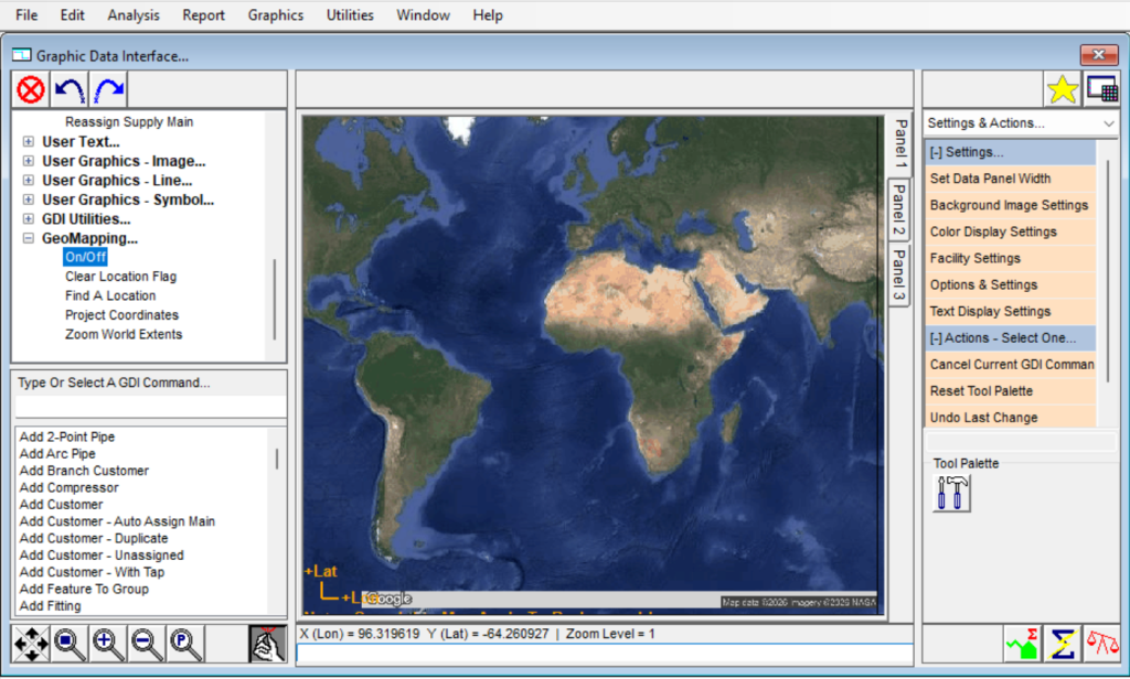
As with the previous workflow, the coordinate units and background image are set from the Utilities and Graphics menus, which have no GDI Command Line aliases; the GeoMapping functions are toggled by selecting the On/Off item from the GeoMapping branch of the GDI Command Tree or by typing GEOMAP on the GDI Command Line and pressing Enter.
Notes
- To find a geographic location, use a place (town) name, a street address, or a geographic name. If using a street address, include the zip or postal code, city name, and state for the most precise result.
- If the background image is not displayed in the GDI Display, go to the Display Settings branch of the GDI Command Tree and select the Display Background Image item.
- Using a plane coordinate system with a Geographic Map background while tracing a new model is difficult. If you want to use both, it is best to build (or partially build) the model in “Web L/L” Coordinate Values units, then project it to a plane coordinate system with the Project Coordinates command and use Zoom To Fit to display the contents and continue working.
Attach a Geographic Map Background to an Existing Model
- Open the existing model. From the File menu select Open, navigate to the model file, and click Open. If the GDI Window does not display automatically, select the View/Edit item from the Graphics menu; then resize it using the Maximize GDI Window item on the GDI Utilities branch of the GDI Command Tree.
- Check the coordinate system. Move the mouse over the GDI Display and read the coordinate values in the Information Panel at the bottom of the screen. WCS values range from -180 to 180 for Longitude and -90 to 90 for Latitude; large numbers outside that range indicate plane coordinates that must be re-projected or backed by a projection file.
- Prepare the model — choose one option. Re-project to WCS: select Project Coordinates from the GeoMapping branch, choose “Plane Coordinates To Longitude/Latitude” and file type “ESRI Projection (*.prj),” browse to the matching .prj file, and Continue; the Coordinate Values unit changes to “Web L/L.” Or attach a projection file: select Attach ‘prj’ Style Projection File from the GDI Command List and choose the matching .prj file.
- Enable the GeoMapping functions. Select the On/Off item from the GeoMapping branch of the GDI Command Tree, read the message carefully, and click Yes to continue.
- Attach the map background. From the Graphics menu select Background Settings, click Attach New Image, choose “Geographic Map Service,” and Continue. Select a Map Service (for example, Map Box) and a Map Type (for example, Combination Street Map & Satellite Image), click Apply, then click Yes to accept the service’s terms. An image of the entire world is displayed.
- Zoom to the model. Click the Zoom To Fit icon; the piping should now overlay the Geographic Map background image in its actual location.
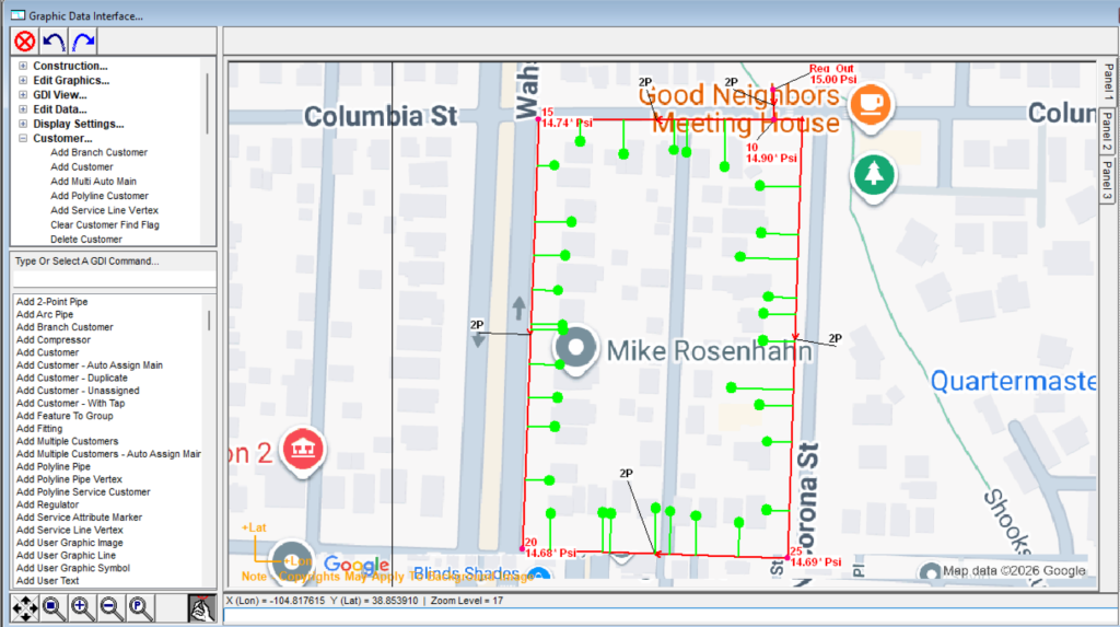
This workflow is driven from menus and the GDI Command Tree rather than a single command: the GeoMapping functions are toggled by selecting the On/Off item from the GeoMapping branch of the GDI Command Tree or by typing GEOMAP on the GDI Command Line and pressing Enter, and the background image is attached from the Background Settings item on the Graphics menu, which has no GDI Command Line alias.
Notes
- Overlaying an existing model is only possible when an appropriate projection file is available, allowing you to either attach it or re-project the coordinates to WCS values. If the original coordinate system is unknown and/or no appropriate projection file is available, the coordinates cannot be re-projected.
- Projection files are unique to each coordinate system and vary by geographic location. A projection file (.prj) is often included in a shapefile set, so if the model was originally built by importing shapefile data, that shapefile’s projection file can be used to re-project the coordinates.
Notes & Considerations
- When a model is overlaid on — or traced over — a Geographic Map background image, pipe lengths are calculated from the image coordinates. The Web Mercator Projection distorts north-south distances for areas away from the Equator; the distortion grows with distance and, although not necessarily large, should be checked to ensure lengths are appropriate for the intended use.
- It can be beneficial to change the default display sizes and colors so that features such as pipes and nodes are easier to see against the map imagery. Use the various display, graphic, and text settings to make appropriate changes.
- A detailed description of the terms of use and privacy policy for the selected map service can be viewed from the Third Party Terms & Conditions submenu of the Help menu. You must agree to these terms to use the GeoMapping functions.
- Only one map service may be used at a time, and coverage, imagery age, and resolution vary by service and area. For tile-based services, clear the tile cache periodically with the Clear GeoMapping Tiles command so new or updated tiles are downloaded.
- Not all GeoMapping functions are available unless the model’s Coordinate Values are in “Web L/L” units. See the GASWorkS User’s Manual for additional information on working with the GeoMapping functions.
See Also
- Coordinates, Projection & Snapping
- Toggling Layers, Logs & GeoMapping
- Display & Visibility Settings
- Finding Locations, Text & Crossings
- Views, Panning, Zooming & Plotting
- Example: Importing DXF & Working with Shapefiles
- Example: Selecting, Moving & Viewing Features
FAQ
-
What do I need before I can use the GeoMapping functions?First, a continuous internet connection, because the imagery is streamed or downloaded directly from the map service and the geolocating engine also runs over the connection. You will also need your model to be usable in World Coordinate System values — ideally the “Web L/L” Coordinate Values unit — either natively or by attaching a projection file or re-projecting the coordinates. Finally, you will have to accept the selected map service’s terms of use and privacy policy the first time you attach its imagery.
-
Why is the “Web L/L” coordinate unit so important for GeoMapping?model displays best over a Geographic Map background when it uses the Web Mercator Projection, which locates points by WCS Longitude and Latitude. GASWorkS represents that projection with the “Web L/L” Coordinate Values unit, entered in decimal degrees as Longitude (X) then Latitude (Y) — the reverse of the usual Lat/Long order. Not all GeoMapping functions are available when the model’s coordinates are not in “Web L/L” units.
-
My existing model uses plane coordinates. How do I get it onto a map background?You can either re-project the coordinates to WCS values with the Project Coordinates command, or attach a matching projection (.prj) file with the Attach ‘prj’ Style Projection File command. Either approach requires an appropriate projection file for the model’s region. If the original coordinate system is unknown and no suitable projection file exists, the coordinates cannot be re-projected.
-
Are the pipe lengths accurate when I draw over a map background?They should be checked. When a model is overlaid on or traced over a Geographic Map background, pipe lengths are calculated from the image coordinates, and the Web Mercator Projection distorts north-south distances for areas away from the Equator. The distortion grows with distance from the Equator and, although not always large, should be verified so the lengths are appropriate for the intended use.
-
Where do projection files come from?Projection files are unique to each coordinate system and vary by geographic location. A .prj file is often included in a shapefile set, so if the model was originally built by importing shapefile data, that shapefile’s projection file can usually be reused to re-project the coordinates.
-
How do I turn the GeoMapping functions on or off?Select the On/Off item from the GeoMapping branch of the GDI Command Tree, or type GEOMAP on the GDI Command Line and press Enter. A confirmation message appears, and you should click Yes to continue. The imagery itself is then attached from the Background Settings item on the Graphics menu.
-
The map background isn’t showing up — what should I check?If the background image is not displayed in the GDI Display, go to the Display Settings branch of the GDI Command Tree and select the Display Background Image item. It is also worth confirming that the GeoMapping functions are enabled and that the terms of use were accepted. For tile-based services, clearing the tile cache with the Clear GeoMapping Tiles command forces new or updated tiles to download.