
Introduction
A submerged pipeline’s tendency to float is governed by a balance of weights: the steel pipe itself, the water it displaces, any liquid it carries, and the backfill above it. This calculator evaluates that balance with the pipe treated as empty — a deliberately conservative assumption that both sets aside the stabilizing weight of any product and accounts for periods when the line may be out of service.
From that balance the calculator sizes the concrete coating required to hold the line down. It solves for the concrete coating thickness that makes the coated, empty pipe heavy enough to overcome buoyancy while still meeting the specified safety factor and negative buoyancy margin against the weight of water displaced.
The analysis is driven by the unit weight of water entered in PLTB; it does not account for water depth or depth of burial.
Determine Bare Pipe Weight
W_{pipe}=10.68\,(D-t)\,t \quad [\text{lbs/ft}]W_{pipe}=10.68\,(D-t)\,t \quad [\text{lbs/ft}]
Where:
D − Pipe outside diameter (in)
t − Pipe wall thickness (in)
Determine Volume of Corrosion Coating
V_{corr}=\frac{\pi\,(D+2t_{corr})^2}{4(144)}-\frac{\pi D^2}{4(144)} \quad [\text{ft}^3]V_{corr}=\frac{\pi\,(D+2t_{corr})^2}{4(144)}-\frac{\pi D^2}{4(144)} \quad [\text{ft}^3]
Where:
tcorr = Corrosion coating thickness (in)
Determine Required Concrete Coating Thickness
The coating is sized against a design water unit weight that folds in both the safety factor and the negative buoyancy margin:
\gamma = \rho_{w}\cdot SF\cdot\left(1+\frac{\%b}{100}\right)\gamma = \rho_{w}\cdot SF\cdot\left(1+\frac{N}{100}\right)
Where:
γ = Design water unit weight (lb/ft3)
ρw = Specific weight of water (lb/ft3)
SF = Safety factor
%b = Negative buoyancy (%)
The required thickness tcon is the larger real root of the quadratic A·tcon2 + B·tcon + C = 0. The coefficients below produce a thickness in feet, which is then converted to inches:
\begin{aligned}
A &= \pi\,(\gamma-\rho_{con})\\[2pt]
B &= \frac{\pi}{12}\,(D+2t_{corr})\,(\gamma-\rho_{con})\\[2pt]
C &= \frac{\pi}{144}\left[\frac{\gamma}{4}\,(D+2t_{corr})^2-\rho_{corr}\,(D\,t_{corr}+t_{corr}^2)\right]-W_{pipe}
\end{aligned}
\begin{aligned} A &= \pi\,(\gamma-\rho_{con})\\ B &= \frac{\pi}{12}\,(D+2t_{corr})\,(\gamma-\rho_{con})\\ C &= \frac{\pi}{144}\left[\frac{\gamma}{4}\,(D+2t_{corr})^2-\rho_{corr}\,(D\,t_{corr}+t_{corr}^2)\right]-W_{pipe} \end{aligned}
t_{con}=\max\!\left(\frac{-B \pm \sqrt{B^{2}-4AC}}{2A}\right)\times 12 [\text{in}]t_{con}=\max\!\left(\frac{-B \pm \sqrt{B^{2}-4AC}}{2A}\right)\times 12 \quad [\text{in}]
Where:
tcon = Concrete coating thickness (in)
ρcon = Concrete coating specific weight (lb/ft3)
ρcorr = Corrosion coating specific weight (lb/ft3)
Before a thickness is reported, two conditions are tested:
- If the concrete coating density is less than the design water unit weight (ρcon < γ), no solution is possible — the concrete is not dense enough to overcome buoyancy.
- If C < 0, the pipe already fulfills the specified safety factors without concrete coating, so no coating is necessary.
Determine Volume of Concrete Coating
V_{con}=\frac{\pi}{4(144)}\left[(D+2t_{corr}+2t_{con})^2-(D+2t_{corr})^2\right] \quad [\text{ft}^3]V_{con}=\frac{\pi}{4(144)}\left[(D+2t_{corr}+2t_{con})^2-(D+2t_{corr})^2\right] \quad [\text{ft}^3]
Determine Total Volume of Pipe in Air Including Corrosion and Concrete Coating
V_{total}=\frac{\pi\,(D+2(t_{corr}+t_{con}))^2}{4(144)} \quad [\text{ft}^3]V_{total}=\frac{\pi\,(D+2(t_{corr}+t_{con}))^2}{4(144)} \quad [\text{ft}^3]
Determine Total Weight of Pipe in Air, Including Weight of Corrosion and Concrete Coating
W_{total}=W_{pipe}+V_{corr}\,\rho_{corr}+V_{con}\,\rho_{con} \quad [\text{lbs/ft}]W_{total}=W_{pipe}+V_{corr}\,\rho_{corr}+V_{con}\,\rho_{con} \quad [\text{lbs/ft}]
Where:
ρcorr = Corrosion coating specific weight (lb/ft3)
ρcon = Concrete coating specific weight (lb/ft3)
Determine Weight of Displaced Water
W_{water}=V_{total}\,\rho_{w} \quad [\text{lbs/ft}]W_{water}=V_{total}\,\rho_{w} \quad [\text{lbs/ft}]
Where:
ρw = Specific weight of water (lb/ft3)
Determine the Difference (Weight of Submerged Pipe)
F=W_{total}-W_{water} \quad [\text{lbs/ft}]F=W_{total}-W_{water} \quad [\text{lbs/ft}]
A positive result means the coated, empty pipe is negatively buoyant — it sinks — by that net weight per foot.
Determine Weight Per Joint
W_{joint}=W_{total}\cdot L \quad [\text{lbs/joint}]W_{joint}=W_{total}\cdot L \quad [\text{lbs/joint}]
Where:
L = Pipe length per joint (ft)
Verify Negative Buoyancy
As a final check, the achieved negative buoyancy margin is computed and compared against the target value entered as an input. When the coating has been sized correctly, the achieved margin equals the specified negative buoyancy:
\%b=\left(\frac{W_{total}}{W_{water}\cdot SF}-1\right)\times 100 \quad [\%]N=\left(\frac{W_{total}}{W_{water}\cdot SF}-1\right)\times 100 \quad [\%]
Where:
%b = Negative buoyancy margin (%)
Wtotal = Weight of pipe in air (lbs/ft)
Wwater = Weight of displaced water (lbs/ft)
SF = Safety factor
Case Guide
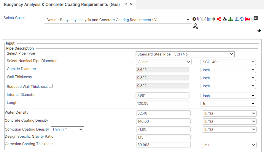
Part 1: Create Case
- Select the Buoyancy Analysis & Concrete Coating Requirements application from the Design & Stress Analysis Module
- To create a new case, click the “Add Case” button
- Enter Case Name, Location, Date and any necessary notes.
- Fill out all required Parameters.
- Make sure the values you are inputting are in the correct units.
- Click the CALCULATE button to overview results.
Input Parameters
- Nominal Outside Diameter (in): (0.625” – 48”)
- Wall Thickness (in): (0.068” – >2”)
- Pipe Grade: (24,000 psi – 80,000 psi) (if unknown use Grade A 24,000)
- Pipe Length (ft/joint)
- Water Density (lb/ft³): (59 – 64)
- Concrete Coating Density (lb/ft³): (50 – 170)
- Corrosion Coating Density (lb/ft³): (50 – 100)
- Safety Factor (e.g., 1.15)
- Negative Buoyancy (%) (e.g., 1)
- Corrosion Coating Thickness (mil): (1 – 50 mils)
Part 2: Outputs/Reports
- If you need to modify an input parameter, click the CALCULATE button after the change.
- To SAVE, fill out all required case details then click the SAVE button.
- To rename an existing file, click the SAVE As button. Provide all case info then click SAVE.
- To generate a REPORT, click the REPORT button.
- The user may export the Case/Report by clicking the Export to Excel icon.
- To delete a case, click the DELETE icon near the top of the widget.
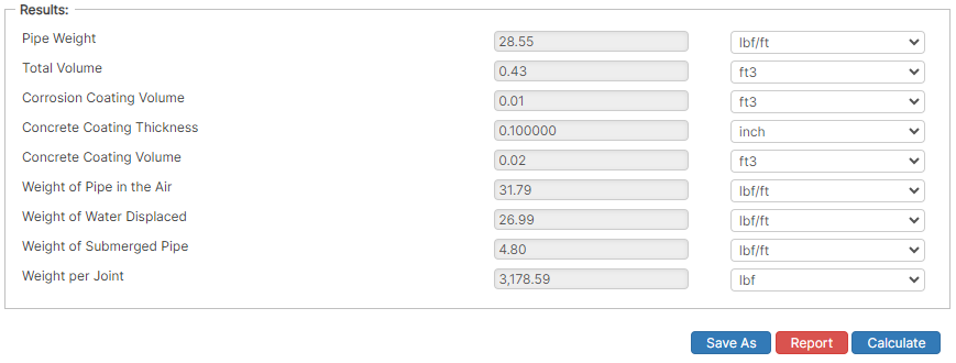
Results
- Pipe Weight (lbs/ft)
- Total Volume (ft³)
- Corrosion Coating Volume (ft³)
- Concrete Coating Thickness (in): (0.25” – 8.5”)
- Concrete Coating Volume (ft³)
- Weight of Pipe in Air (lbs/ft): (21 – 1750)
- Weight of Water Displaced (lbs/ft): (3 – 1600)
- Weight of Submerged Pipe (lbs/ft): (2 – 250)
- Weight Per Joint (lbs/joint): (800 – 70,000)

References
- ASME B31.8 – Gas Transmission and Distribution Piping Systems
- API 5L, API 5LS and API 5LX – Specification of Pipe Grade
- ASTM – Various – Weld Joint Factor
- CFR Code Part 192
- USDA-SCS Modified (Permissible Velocity of Water and Soil Erodibility)
- FHWA-HEC
- Pipeline Rules of Thumb Handbook
- Timoshenko, S – Theory of Elasticity Anchor Force
FAQ
-
Restrained versus Unrestrained Pipe (Difference in Gas vs. Liquid)?
ASME B31.4 liquid and B31.8 gas codes include calculations for the net longitudinal compressive stress that must be applied only for a restrained line that equates to a low (less than 2%) longitudinal strain. This stress status is characteristic to underground pipelines located some distance away from above ground piping facilities.
Unrestrained lines means those above ground sections of piping without axial restraint as with buried pipe with soil. In others words the soil exerts substantial axial restraint, but not fully restrained. Check Out
-
What is the Maximum Span Length of rev1?
Regarding span factors with and without water are based on bending stress and deflection. Larger diameter pipe spans require saddles for stability. Many standards that require pipes to be filled with water are based on bending and shear stresses not to exceed 1,500 psi and a deflection between supports not exceed 0.1 inches. Check Out
-
What is the model used for Thrust at Blow-Off?