
Introduction
The IGT – Improved calculator computes the volumetric flow rate, pressure drop, pipe diameter, or pipe length for a gas pipe segment using the Institute of Gas Technology Improved flow equation. Developed in the 1960s, the IGT-Improved equation is one of the most widely applied pipe flow equations in the natural gas industry, suitable for distribution, transmission, gathering, and plant piping across a broad range of operating pressures (1–500 psig). The equation accounts for gas-specific gravity, viscosity, compressibility, pipe diameter, pipe length, and a user-defined pipe efficiency.
Important: The IGT-Improved equation is Reynolds Number dependent. It applies to distribution systems where Reynolds Numbers range from approximately 16,000 to 3,000,000 with 2% deviation from the smooth pipe law. Applicable diameter and pressure ranges, as documented in the AGA GEOP text, are: 3–30 inch pipe at inches water column, 1.5–20 inch pipe at 2–20 psig, and 0.75–120 inch pipe at 20–100 psig. Using the equation outside these ranges may yield inaccurate results.
Background
Gas pipe flow equations relate the volumetric flow rate through a pipe segment to the pressure drop across it, accounting for the resistance imposed by pipe geometry and gas properties. All such equations share the general principle that flow increases with increasing pressure drop and decreases with increasing resistance. However, each equation was developed empirically for a particular flow regime or application, and no single equation accurately reflects all possible conditions in all types of gas piping systems.
The IGT-Improved equation was published in 1967 in Gas Age Magazine and is derived from smooth-pipe law friction factor behaviour. It was developed specifically for distribution systems but has become the de facto general-purpose equation in the software for medium and high pressure distribution, lower-pressure transmission, gathering, and plant piping applications. The Gas Engineers Handbook notes that it is widely used for ten-inch water column to sixty psig systems for two-inch and larger diameter pipe.
Pipe Efficiency
All pipe flow equations include a hydraulic efficiency term (E). This parameter allows the user to tune the equation to better match actual field measurements. An efficiency of less than 1.0 provides a conservative safety factor; an efficiency greater than 1.0 increases the predicted capacity. For the IGT-Improved equation, efficiencies between 0.80 and 1.20 are typical for well-matched applications — values outside this range may indicate either incorrect input data or a poor equation-to-application fit.
Compressibility
The IGT-Improved equation includes the compressibility factor Z in its pressure drop term. Ignoring compressibility (setting Z = 1.0) produces conservative results — lower flow rates, higher pressure drops, or larger calculated pipe sizes than if compressibility were accounted for. For design calculations this is generally acceptable at pressures below 100 psig; above 400 psig, the gas begins to deviate significantly from ideal behavior, and an accurate compressibility constant becomes necessary. For measurement calculations a compressibility factor method should always be applied.
Elevation Effects
When inlet and outlet elevations differ, two corrections are applied. First, the atmospheric pressure at each end is adjusted for elevation, affecting the absolute pressure used in the calculation. Second, when the pressure difference term is expressed as a squared-pressure difference (ΔP = P₁² − P₂²), the hydrostatic head of the gas column is accounted for by replacing ΔP with an elevation-compensated form (described in the Equations section). Both effects are computed automatically when inlet and outlet elevations are entered.
Equations
IGT-Improved Flow Equation
As implemented in GASCalc, the Institute of Gas Technology Improved flow equation is:
Q = 664.3 \times \frac{T_B}{P_B} \times \frac{1}{\mu^{0.111}} \times \left(\frac{\Delta P}{SG^{0.8} \times T_F \times L \times Z}\right)^{0.556} \times D^{2.667} \times EQ = 664.3 \times \frac{T_B}{P_B} \times \frac{1}{\mu^{0.111}} \times \left(\frac{\Delta P}{SG^{0.8} \times T_F \times L \times Z}\right)^{0.556} \times D^{2.667} \times E
Where:
Q − Volumetric flow rate at the specified base pressure and temperature (ft3)
TB − Base temperature (°R)
PB − Base pressure (psia)
μ − Absolute (dynamic) viscosity of the gas (lbm/ft·sec)
ΔP − Pressure difference term (psia2)
SG − Specific gravity of the gas (dimensionless)
TF − Average gas flowing temperature (°R)
L − Pipe length (ft)
Z − Compressibility factor
D − Inside pipe diameter (in)
E − Pipe hydraulic efficiency (0-1)
Where for standard (non-elevation-adjusted) calculations:
\Delta P = P_1^2 - P_2^2
\Delta P = P_1^2 – P_2^2
Where:
ΔP − Pressure difference term (psia2)
P1 − Pipe inlet (upstream) absolute pressure (psia)
P2 − Pipe outlet (downstream) absolute pressure (psia)
Elevation Adjustment
When an elevation difference exists between the pipe inlet and outlet, the ΔP term is replaced by an elevation-compensated pressure difference to account for the hydrostatic head of the gas column:
\Delta P = P_1^2 - e^S \times P_2^2
\Delta P = P_1^2 – e^S \times P_2^2
Where:
ΔP − Pressure difference term (psia2)
P1 − Pipe inlet (upstream) absolute pressure (psia)
P2 − Pipe outlet (downstream) absolute pressure (psia)
e − Napier’s constant (2.71828)
S − Elevation compensation factor (dimensionless)
S = \frac{0.0375 \, SG \, (E_1 - E_2)}{T_F \times Z}S = \frac{0.0375 \, SG \, (E_1 – E_2)}{T_F \times Z}
Where:
S − Elevation compensation factor
SG − Specific gravity of the gas
E1 − Pipe inlet elevation (ft)
E2 − Pipe outlet elevation (ft)
TF − Average gas flowing temperature (Napier’s constant)
Z − Compressibility factor
Recommended Applications
The following table summarises the applications for which the IGT-Improved equation is recommended, alongside competing equations for comparison:
| Application | Recommended Equation(s) |
|---|---|
| Low Pressure Distribution (< 3 psig) | Spitzglass — Low Pressure |
| Medium and High Pressure Distribution (3–100 psig) | IGT-Improved |
| Low Pressure Transmission (100–300 psig) | IGT-Improved |
| High Pressure Transmission (≥ 300 psig) | Panhandle-A |
| Low Pressure Gathering (< 100 psig) | IGT-Improved |
| High Pressure Gathering (≥ 100 psig) | IGT-Improved, Weymouth |
| Medium Pressure Plant or Fuel Piping (1.5–10 psig) | IGT-Improved, IFGC-HP, IAPMO-HP, IMC-HP |
| High Pressure Plant or Fuel Piping (10–100 psig) | IGT-Improved, Oliphant |
Case Guide
Part 1: Create Case
- Select the IGT – Improved application from the Hydraulics Module.
- From the Pipe menu, select the Pipe Flow item. The Pipe Flow calculation screen will be displayed.
- Click the Clear button to set all values to blank (null).
- Click the Base Conditions button. Enter the base pressure and temperature, select or enter gas property values (specific gravity, viscosity), choose the Atmospheric Pressure Method, and optionally select a Compressibility Factor Method. Click Apply to save and return.
- On the Pipe Data tab, select Institute of Gas Technology – Improved from the Pipe Flow Equation dropdown.
- Click the red label of the item to be calculated — Diameter, Length, Flow Rate, Inlet Pressure, or Outlet Pressure — until it is underlined.
- Click the ? button next to Diameter to select a pipe size from the Pipe Property Table, or enter the inside diameter directly. Enter Length, Efficiency, and Flow Rate in the Segment Data section.
- In the End Conditions section, enter the known Inlet Pressure and/or Outlet Pressure, Inlet Elevation, Outlet Elevation, Inlet Temperature, and Outlet Temperature. Select appropriate dimensional units for each field.
- If fittings or additional pipe components are attached, use the Other Data tab to manage the Additional Components list.
- To include heat loss or gain along the segment, select the appropriate method on the Heat Loss/Gain Data tab; otherwise leave the Calculation Method set to None.
- Click the Calculate button to compute results.
Input Parameters
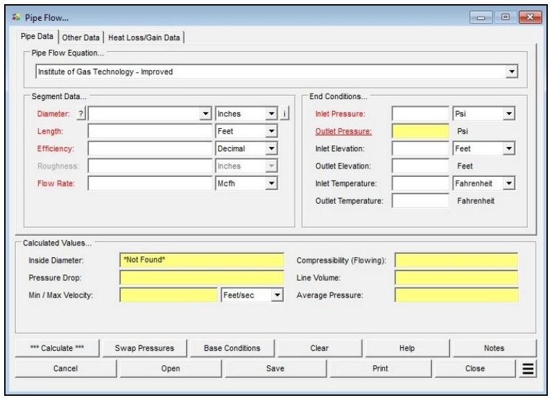
| Parameter | Description |
|---|---|
| Pipe Flow Equation | Specifies the flow equation to use during the calculation. Set to Institute of Gas Technology – Improved for this calculator. |
| Diameter | Specifies or displays the hydraulic (inside) diameter of the pipe segment. Click the ? command button to select a size using the Pipe Selection screen. Click the red label to select this as the unknown to be solved. |
| Length | Specifies or displays the hydraulic length of the pipe segment. Click the red label to select this as the unknown to be solved. |
| Efficiency | Specifies or displays the hydraulic efficiency value of the pipe segment. Click the red label to select this as the unknown to be solved. |
| Roughness | Specifies the internal wall roughness of the pipe segment. Not used by the IGT-Improved equation. |
| Flow Rate | Specifies or displays the flow rate through the pipe segment. Click the red label to select this as the unknown to be solved. |
| Inlet Pressure | Specifies or displays the pressure at the inlet (upstream) end of the pipe segment. Click the red label to select this as the unknown to be solved. |
| Outlet Pressure | Specifies or displays the pressure at the outlet (downstream) end of the pipe segment. Click the red label to select this as the unknown to be solved. |
| Inlet Elevation | Specifies the height above mean sea level at the inlet end. Displayed when the Atmospheric Pressure Method is not set to “None” or “None – Entered Value.” |
| Outlet Elevation | Specifies the height above mean sea level at the outlet end. Displayed when the Atmospheric Pressure Method is not set to “None” or “None – Entered Value.” |
| Inlet Temperature | Specifies the flowing temperature at the inlet (upstream) end of the pipe segment. |
| Outlet Temperature | Specifies the flowing temperature at the outlet (downstream) end. Calculated when Heat Loss/Gain method is active or the Joule-Thomson effect option is selected. |
| Inlet Atm Press | Specifies the atmospheric pressure at the inlet end. Displayed only when the Atmospheric Pressure Method is set to “None – Entered Value.” |
| Outlet Atm Press | Specifies the atmospheric pressure at the outlet end. Displayed only when the Atmospheric Pressure Method is set to “None – Entered Value.” |
Part 2: Outputs/Reports
- If you need to modify an input parameter, update the value and click the CALCULATE button again.
- To swap inlet and outlet conditions (useful when calculating a series of contiguous pipe segments), click the Swap Pressures button.
- To SAVE, click the Save command button. Provide a file name and location (.clc file).
- To open a previously saved calculation, click the Open command button and select the .clc file.
- To generate a REPORT, click the Print command button to access the Print Settings screen.
- To calculate results across a range of flow rates, pressures, or lengths, use Additional Actions > Calculate Table of Results.
- To compare results for different pipe sizes or operating conditions, use Additional Actions > Open Duplicate Calculation.
- To add a title or notes to the calculation, click the Notes command button.
Results
| Output | Description |
|---|---|
| Inlet Pressure | The calculated pressure at the inlet (upstream) end of the pipe segment. Displayed when selected as the unknown to be solved (psig or millibar). |
| Outlet Pressure | The calculated pressure at the outlet (downstream) end of the pipe segment. Displayed when selected as the unknown to be solved (psig or millibar). |
| Diameter | The calculated inside pipe diameter. Displayed when selected as the unknown to be solved (inches or mm). |
| Length | The calculated pipe segment length. Displayed when selected as the unknown to be solved (feet or m). |
| Efficiency | Specifies or displays the hydraulic efficiency value of the pipe segment. Click the red label to select this as the unknown to be solved. |
| Flow Rate | The calculated flow rate through the pipe segment. Displayed when selected as the unknown to be solved (cfh, Mcfh, or m³/h). |
| Inside Diameter | The pipe bore read from the Pipe Property Table when a Size/Type Code is selected (inches or mm). |
| Pressure Drop | The total linear pressure drop across the segment, including any attached components (psi or millibar). |
| Min / Max Velocity | The gas velocity at the inlet and outlet end conditions respectively (ft/sec or m/sec). |
| Compressibility (Flowing) | The average compressibility factor computed at the average pressure and temperature along the segment (dimensionless). |
| Line Volume | The volume of gas contained in the pipe segment at base conditions, computed from the average pressure, temperature, and compressibility factor (Mcf or m³). |
| Average Pressure | The calculated average pressure along the segment, used for compressibility and line volume computations (psig or millibar). |
References
- Industrial Press — Gas Engineers Handbook, 1965.
- American Gas Association — Gas Engineering and Operating Practices: System Design, GEOP Series Book D-1, 1990.
- Gas Processors Suppliers Association — Engineering Data Book, Eleventh Edition (FPS), 1998.
- Gas Age Magazine — “Gas Behavior in Distribution Systems,” May 1967. (Primary source for the IGT-Improved equation.)
FAQ
-
Gas Purging Calculations?
Purging is a process of removing gas from the pipeline. Controlled purging of gases from pipelines by direct displacement with other gases that have been safely practiced for many years with the recognition that some flammable mixture is present. Purging of gases from pipelines by direct displacement with another gas also has been similarly practiced. It works both ways; however, there will always be an atmosphere of type of a mixture. This is due to the densities of the gases. Check Out
-
What is Erosional Velocity?
Pipe erosion begins when velocity exceeds the value of C/SQRT(ρ) in ft/s, where ρ = gas density (in lb./ft3) and C = empirical constant (in lb./s/ft2) (starting erosional velocity). We used C=100 as API RP 14E (1984). However, this value can be changed based on the internal conditions of the pipeline. Check Out
-
What is Sonic Velocity?
The maximum possible velocity of a compressible fluid in a pipe is called sonic velocity. Oilfield liquids are semi-compressible, due to dissolved gases. Check Out
-
What is Pipe Roughness?
Pipe roughness is a material property that refers to the absolute roughness of the internal pipe wall surface, used in friction factor calculations for pressure drop and flow calculations. These roughness values may be auto-populated by selecting the “Select Pipe Roughness” dropdown, or by manually inputting the value specified by the manufacturer.