
Introduction
The Pipe Span & Support Analysis application checks an above-ground or exposed gas pipeline span. It covers aerial spans (pipe racks, aerial crossings, exposed spans at river and stream crossings) and submerged spans, where buoyancy, drag and lift are included in the loading.
The application calculates bending moment, shear and deflection along the full length of the span for every load combination you select. It then combines bending, axial and hoop stresses and compares them with the allowable limits of ASME B31.8. The result shows the worst-case (maximum) load combination for each result, so you do not have to check each combination by hand. The support reactions from the governing case can then be carried into the Bearing Capacity application to size the support foundations.
Span Programs
Five beam idealizations are available. Pick the one that best matches the support layout and end restraint.
| Program | Spans | Supports | Loading | Typical use |
|---|---|---|---|---|
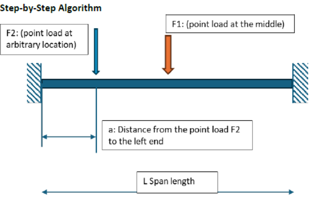
| Fixed Beam Analysis | 1 | Fixed – Fixed | Uniform w, plus F1 (midspan) and F2 (any location) | Single span anchored against rotation at both ends |
| Simply Supported Beam Analysis | 1 | Pin – Roller | Uniform w | Free spans and pipe racks; most conservative single span |
| Double Span – Uniform Load | 2 equal | Pin – Roller – Roller | Uniform w | Pipe continuous over one intermediate support |
| Double Span – Concentrated Load | 2 equal | Pin – Roller – Roller | P at the center of each span | Valves, flanges, fittings; superimpose with self-weight |
| Pipe Multi Span | 3 equal | Pin – Roller ×3 | Uniform w, vertical and horizontal planes | Multi-span crossings and racks with wind; biaxial bending |
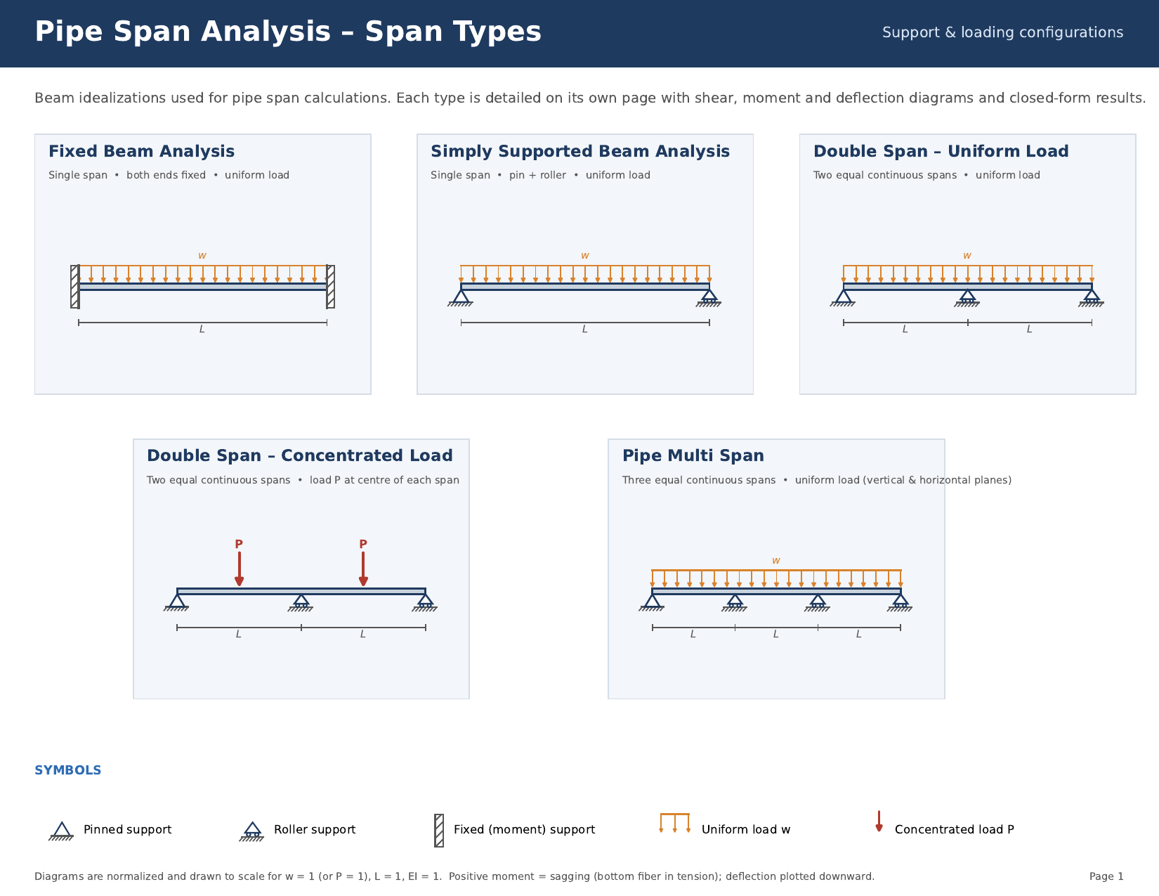
- Simply Supported: use where end restraint is uncertain. It gives the highest moment and deflection for a given span length.
- Fixed Beam: use only where the supports are true anchors. Otherwise support moment and midspan deflection are underestimated.
- Double Span / Pipe Multi Span: use where the pipe is continuous over intermediate supports. Continuity lowers span moment and deflection but increases interior support loads.
- Double Span – Concentrated Load: use for heavy fittings at midspan. Superimpose the uniform-load results for self-weight.
- Pipe Multi Span: use where wind or transverse seismic load makes horizontal bending significant.
Calculation Methodology
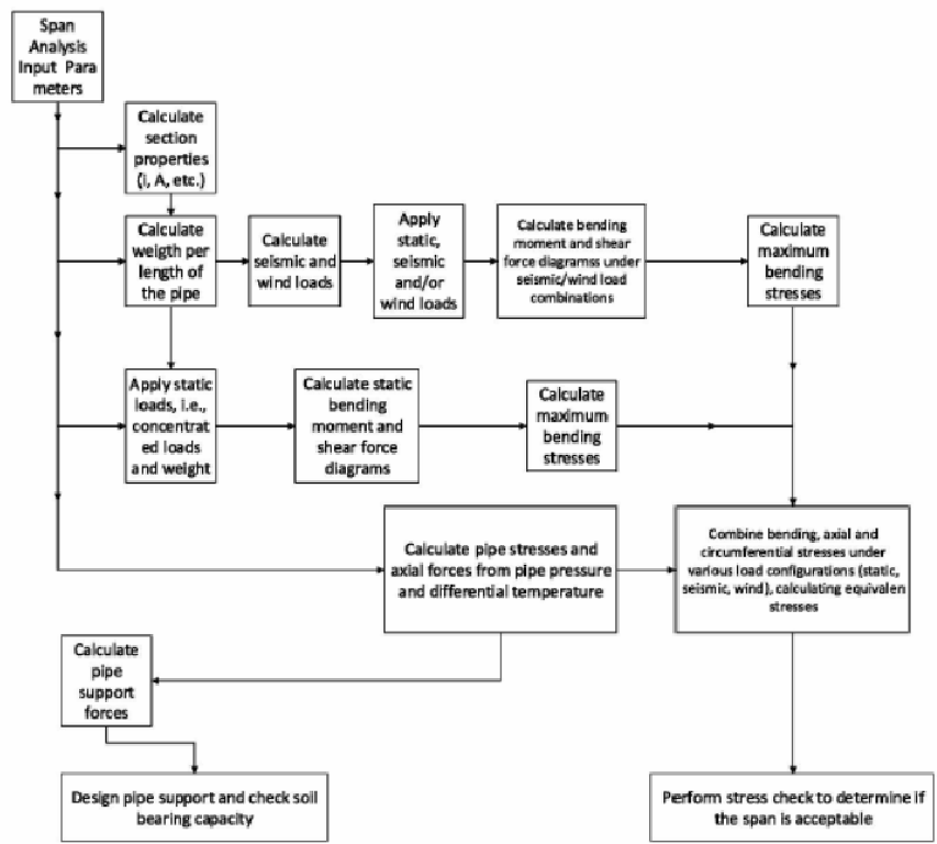
Step 1: Determine the Loads
The loading on a span can come from the weight of the pipe, coating and product; an in-line inspection (ILI) tool; hydrostatic test water; fittings such as valves, regulators and filters; drag, lift and buoyancy on a submerged pipe; wind (per ASCE/SEI 7); and seismic load (per ASME B31E).
Natural gas contributes very little weight to the span. For most gas lines the hydrostatic test (D + H) combination produces the largest gravity load because the pipe is full of test water, so always include it.
| Symbol | Load | Description |
|---|---|---|
| D | Dead load | Pipe, product, coating and fittings. Includes buoyancy for submerged spans. |
| L | Live load | ILI tool weight, applied at midspan. |
| P | Internal pressure | MAOP of the pipeline. |
| ΔT | Differential temperature | Operating temperature minus installed (tie-in) temperature. |
| H | Hydrostatic test | Product weight replaced by test-water weight (typically 10–20% heavier than pure water). |
| W | Wind | Horizontal wind load on the span. |
| ET | Seismic – transverse | Seismic load in the transverse horizontal direction. |
| EA | Seismic – axial | Seismic load along the pipe axis (restrained spans only). |
Step 2: Select the Load Combinations
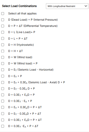
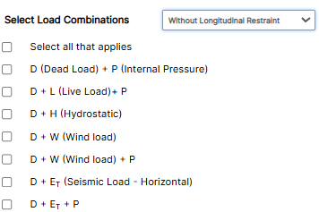
A load combination is a set of loads that can act at the same time. The application uses Allowable Stress Design (ASD), which is consistent with ASME B31.8. Select With Longitudinal Restraint when anchors prevent axial movement, or Without Longitudinal Restraint when the supports allow it. Thermal (ΔT) and axial seismic (EA) combinations appear only for restrained spans, because an unrestrained span relieves these loads by moving.
| No. | Combination | With restraint | Without restraint |
|---|---|---|---|
| 1 | D + P | ✓ | ✓ |
| 2 | D + P + ΔT | ✓ | – |
| 3 | D + L + P | ✓ | ✓ |
| 4 | D + L + P + ΔT | ✓ | – |
| 5 | D + H | ✓ | ✓ |
| 6 | D + H + ΔT | ✓ | – |
| 7 | D + W | ✓ | ✓ |
| 8 | D + W + P | ✓ | ✓ |
| 9 | D + ET | ✓ | ✓ |
| 10 | D + ET + P | ✓ | ✓ |
| 11 | D + ET + 0.3EA + P | ✓ | – |
| 12 | D + ET − 0.3EA + P | ✓ | – |
| 13 | D + 0.3ET + EA + P | ✓ | – |
| 14 | D + 0.3ET − EA + P | ✓ | – |
| 15 | D + ET + 0.3EA + P + ΔT | ✓ | – |
| 16 | D + ET − 0.3EA + P + ΔT | ✓ | – |
| 17 | D + 0.3ET + EA + P + ΔT | ✓ | – |
| 18 | D + 0.3ET − EA + P + ΔT | ✓ | – |
Combinations 11–18 apply the 100%/30% rule for orthogonal seismic components. The full seismic load in one direction acts with 30% in the perpendicular direction, in both signs, so the governing case is captured.
Step 3: Calculate Bending Moment, Shear and Deflection
The span carries a mix of distributed loads (weight, wind, seismic) and concentrated loads (ILI tool, fittings). Instead of checking a few assumed points, the application:
- Divides each span into small intervals, on the order of the pipe OD.
- Calculates moment, shear and deflection at every point for each load combination.
- Searches the results for the maximum and minimum values and their locations.
- Calculates the reaction at each support (used in the Bearing Capacity application).
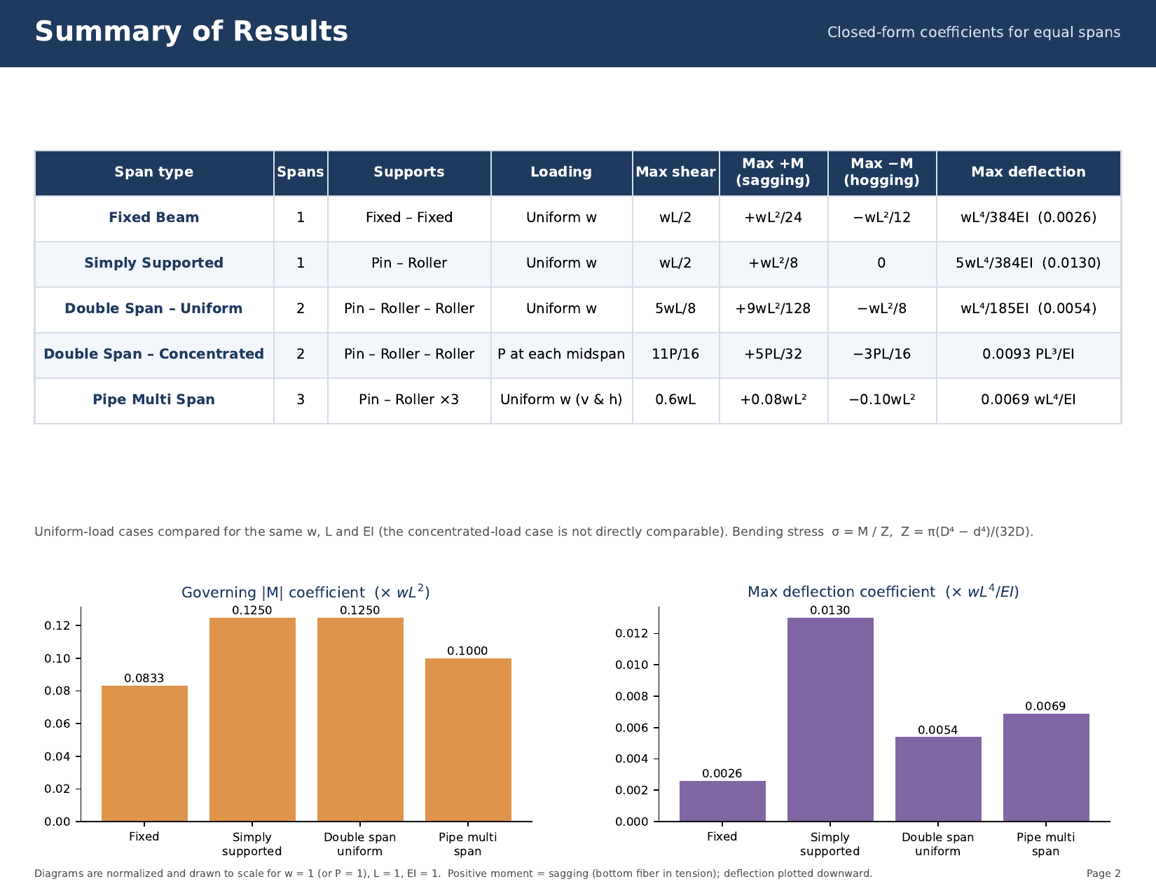
Vertical (gravity) and horizontal (wind, transverse seismic) loads are solved in their own planes. Use the closed-form coefficients below to sanity-check the program output.
| Span type | Max shear | Max +M | Max −M | Max deflection |
|---|---|---|---|---|
| Fixed Beam | wL/2 | +wL²/24 | −wL²/12 | wL⁴/384EI |
| Simply Supported | wL/2 | +wL²/8 | 0 | 5wL⁴/384EI |
| Double Span – Uniform | 5wL/8 | +9wL²/128 | −wL²/8 | wL⁴/185EI |
| Double Span – Concentrated | 11P/16 | +5PL/32 | −3PL/16 | 0.0093PL³/EI |
| Pipe Multi Span | 0.6wL | +0.08wL² | −0.10wL² | 0.0069wL⁴/EI |
Step 4: Calculate Pipe Stresses
Maximum Allowable Operating Pressure:
MAOP=\frac{2\,SMYS\,t}{D}\,F\,E\,T𝐹 − Design Factor (by class location)
𝐸 − Longitudinal Joint Factor
𝑇 − Temperature Derating Factor
Hoop stress (Barlow’s equation):
\sigma_H=\frac{PD}{2t}Longitudinal stress, unrestrained span (supports allow axial movement):
\sigma_a=\frac{PD}{4t}Longitudinal stress, restrained span (supports prevent axial movement):
\sigma_a=\nu\frac{PD}{2t}-\alpha E\Delta TBending stress, and the resultant when bending occurs in both planes:
\sigma_b=\frac{M}{Z},\quad Z=\frac{\pi(D^4-d^4)}{32D}\sigma_b=\sqrt{\sigma_{bv}^2+\sigma_{bh}^2}Where:
𝑃 − Internal Pressure (psi)
𝐷 − Pipe Outside Diameter (in)
𝑑 − Pipe Inside Diameter (in)
𝑡 − Wall Thickness (in)
𝐸 − Modulus of Elasticity (30,000,000 psi, carbon steel)
α − Coefficient of Thermal Expansion (6.5 × 10⁻⁶ in/in/°F, carbon steel)
ν − Poisson’s Ratio (0.3, carbon steel)
Δ𝑇 − Operating minus Installed Temperature (°F)
𝑀 − Bending Moment; 𝑍 − Section Modulus (in3)
Step 5: Combine Stresses and Find the Worst Case
For each selected combination, the application combines bending, axial and hoop stresses into an equivalent stress. It compares the governing stresses with the allowable limits of ASME B31.8 §833 (Design for Longitudinal Stress).
Case Guide
Part 1: Create Case
- Select the Pipe Span & Support Analysis (Gas) application from the Design & Stress Analysis Module.
- To create a new case, click the “Add Case” button.
- Enter Case Name, Location, Date and any necessary notes.
- Select the span program (Fixed, Simply Supported, Double Span – Uniform, Double Span – Concentrated, or Multi Span).
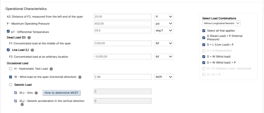
- From Select Load Combinations, choose With or Without Longitudinal Restraint and check every combination that applies.
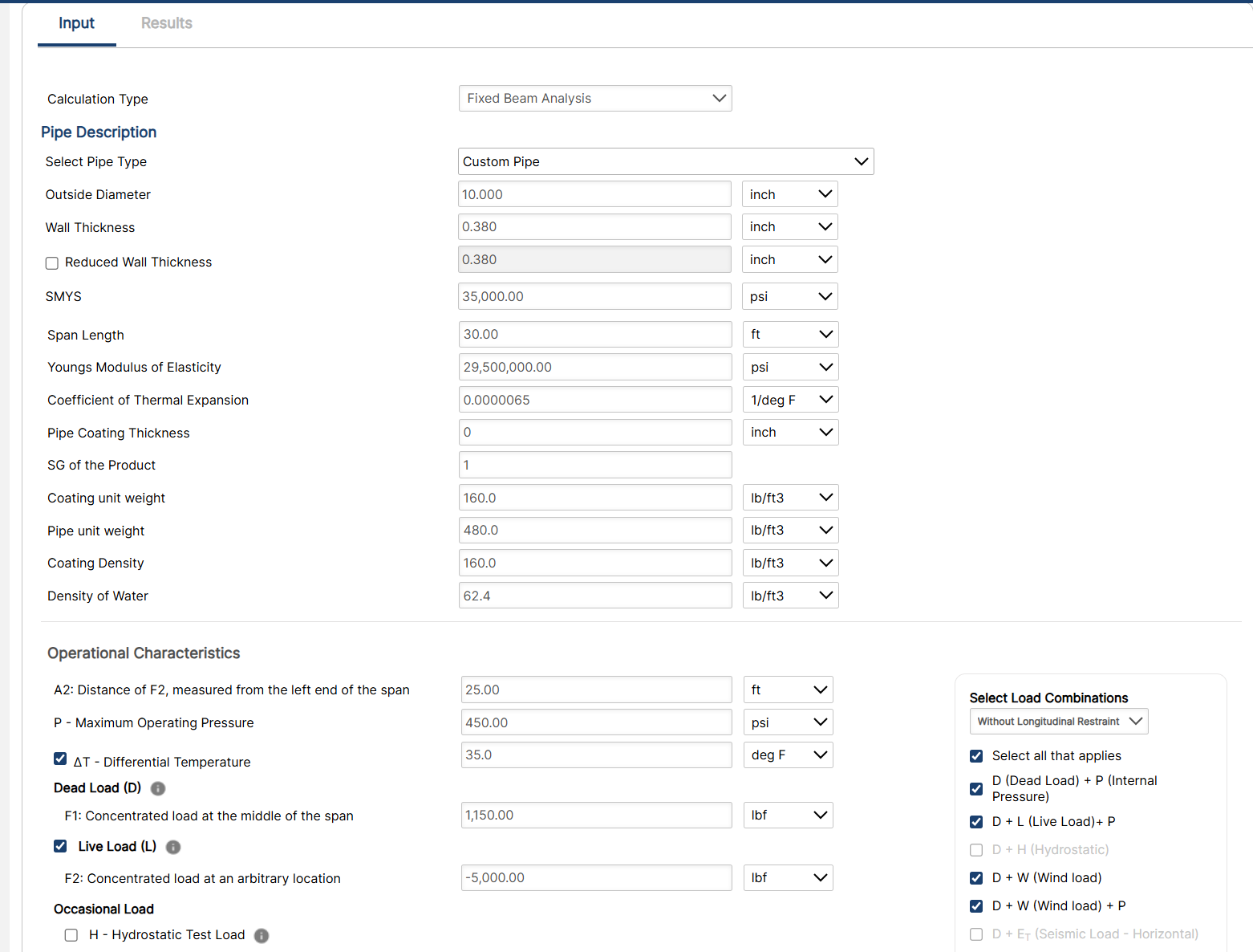
- Fill out all required Parameters.
- Make sure the values you are inputting are in the correct units.
- Click the CALCULATE button to overview results.
Input Parameters
- Outside Diameter, OD (in)
- Wall Thickness, WT (in)
- MAOP (psi)
- Coating Thickness, Tc (in) – significant for thick coatings such as concrete
- Pipe Material Unit Weight, Gm
- Coating Unit Weight, Gc
- Product Unit Weight, Gp
- Span Length, L (ft) – per span for multi-span programs
- Concentrated Load at Midspan, F1 (e.g., ILI tool)
- Concentrated Load at Any Location, F2 (e.g., valve or fitting)
- Distance to F2 from Left End, a2
- Wind Load or Wind Velocity
- Seismic Acceleration, Horizontal (agh)
- Seismic Acceleration, Vertical (agv)
- Elastic Modulus, Em (default 30,000,000 psi)
- Coefficient of Thermal Expansion, α (default 6.5 × 10⁻⁶ in/in/°F)
- Poisson’s Ratio, ν (default 0.3)
- Differential Temperature, ΔT (°F)
- Hydrostatic Test-Water Unit Weight, γw (typically 10–20% above pure water)
Part 2: Outputs/Reports
- If you need to modify an input parameter, click the CALCULATE button after the change.
- To SAVE, fill out all required case details then click the SAVE button.
- To rename an existing file, click the SAVE As button. Provide all case info then click SAVE.
- To generate a REPORT, click the REPORT button.
- The user may export the Case/Report by clicking the Export to Excel icon.
- To delete a case, click the DELETE icon near the top of the widget.
Results
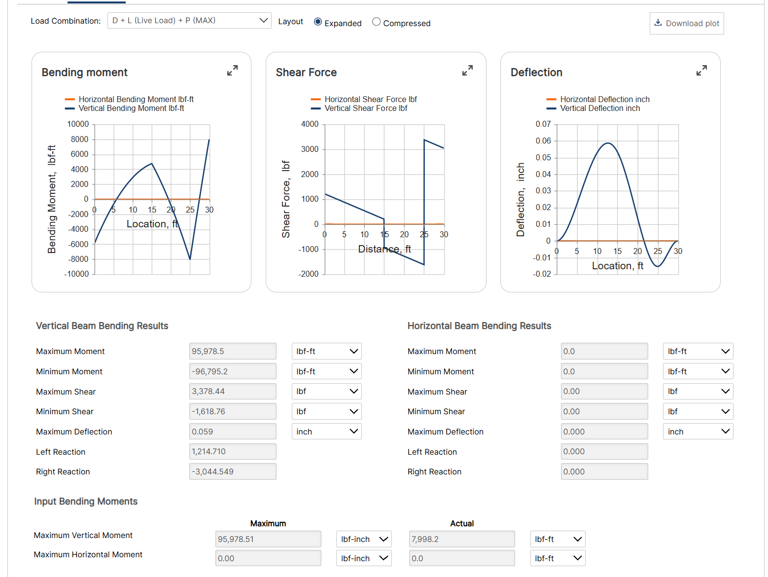
- Support Reactions at each support
- Maximum and Minimum Bending Moment and location
- Maximum and Minimum Shear Force and location
- Maximum Deflection and location
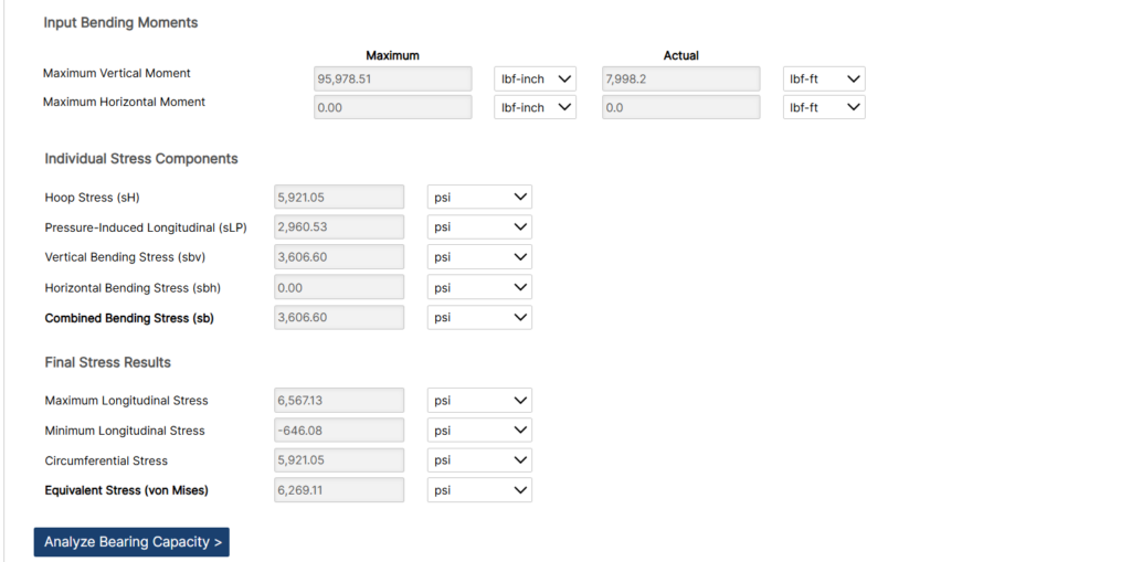
- Hoop, Longitudinal and Bending Stress for each selected load combination
- Equivalent (Combined) Stress for each selected load combination
- Governing (worst-case) load combination for each result
- Pass/Fail Stress Check
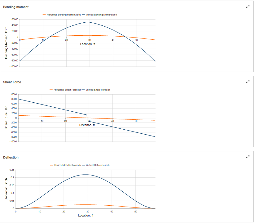
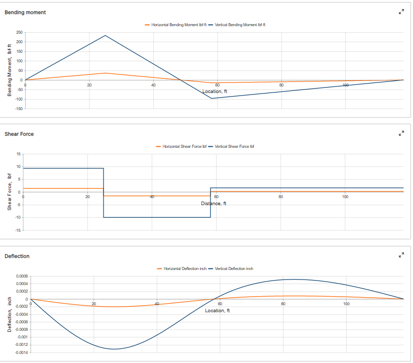
- Bending Moment, Shear and Deflection plots (vertical and horizontal planes)
References
- ASME B31.8 – Gas Transmission and Distribution Piping Systems
- ASME B31E – Seismic Design and Retrofit of Above-Ground Piping Systems
- ASCE/SEI 7 – Minimum Design Loads and Associated Criteria for Buildings and Other Structures
- API 5L – Specification for Line Pipe
- API 579-1/ASME FFS-1 – Fitness-For-Service
- 49 CFR Part 192
FAQ
-
Restrained versus Unrestrained Pipe (Difference in Gas vs. Liquid)?
ASME B31.4 liquid and B31.8 gas codes include calculations for the net longitudinal compressive stress that must be applied only for a restrained line that equates to a low (less than 2%) longitudinal strain. This stress status is characteristic to underground pipelines located some distance away from above ground piping facilities.
Unrestrained lines means those above ground sections of piping without axial restraint as with buried pipe with soil. In others words the soil exerts substantial axial restraint, but not fully restrained. Check Out
-
What is the Maximum Span Length of rev1?
Regarding span factors with and without water are based on bending stress and deflection. Larger diameter pipe spans require saddles for stability. Many standards that require pipes to be filled with water are based on bending and shear stresses not to exceed 1,500 psi and a deflection between supports not exceed 0.1 inches. Check Out
-
What is the model used for Thrust at Blow-Off?