
Introduction
The Pipe Flow application calculates the values associated with the flow of gas through a pipe segment, including flow rate, inlet or outlet pressure, pressure drop, hydraulic diameter, minimum and maximum velocity, average pressure, line volume, and flowing compressibility. The American Gas Association – Turbulent (AGA – Turbulent) equation is one of several flow equations the application supports; this article covers the use of the Pipe Flow application with the AGA – Turbulent equation selected.
No single flow equation accurately reflects every condition that can occur in a gas piping system. The user is responsible for comparing the specific application against each equation’s intended use and selecting an appropriate equation. The AGA – Turbulent equation is intended for transmission systems operating under fully turbulent flow conditions.
Background
Various equations are available for calculating the volumetric flow through a pipe segment. Many were developed for a particular application or set of conditions, but nearly all are derived from a single general pipe flow equation. In general, every form states that the flow in a pipe segment is proportional to the pressure drop across the segment, divided by a combination of the pipe and gas resistance to flow. The larger the pressure drop, the higher the flow rate; the higher the resistance, the lower the flow rate.
Beyond this general relationship, each equation has been modified to reflect a certain flow regime or application-specific set of conditions. Separate equations have been developed to predict laminar or partially turbulent flow in low-pressure distribution systems, and to predict partially or fully turbulent flow in high-pressure, large-diameter, long-length transmission lines. The AGA family of equations falls into the transmission group.
Equation Selection Guidance
The reference documentation provides general application recommendations – offered for use at the User’s own risk – for matching a flow equation to an application. The following table summarizes those recommendations so the AGA – Turbulent equation can be placed in context against the alternatives.
| Application | Recommended Equation |
|---|---|
| Low Pressure Distribution (less than 3 psig) | Spitzglass – Low Pressure |
| Medium and High Pressure Distribution (3 to 100 psig) | Institute of Gas Technology – Improved |
| Low Pressure Transmission (100 to 300 psig) | Institute of Gas Technology – Improved |
| High Pressure Transmission (300 psig and greater) | Panhandle – A |
| Vacuum Gathering | Oliphant |
| Low Pressure Gathering (less than 100 psig) | Institute of Gas Technology – Improved |
| High Pressure Gathering (100 psig and greater) | Institute of Gas Technology – Improved; Weymouth |
Note: The AGA – Turbulent equation is a transmission-style equation for fully turbulent flow. It is moderately conservative relative to other transmission equations and is most appropriate where a fixed relative roughness and the rough pipe law are acceptable.
Pipe Roughness
As implemented in the calculator, the American Gas Association – Turbulent flow equation represents an equation with a fixed roughness parameter. It is applicable to transmission systems with fully turbulent flow conditions and uses a fixed relative pipe roughness with the rough pipe law. The method is moderately conservative compared with other transmission-style equations. It is distinct from the AGA – Fully Turbulent equation, which applies the rough pipe law with a variable roughness parameter, and from the AGA – Partially Turbulent equation, which applies the smooth pipe law.
Because the AGA – Turbulent equation uses a fixed roughness value, the Roughness data item is not used when this equation is selected. In practice, most pipe in natural gas service has a very smooth wall, either from well-manufactured steel or extruded plastic, and the wall condition tends to remain constant over time. Calibration studies of common flow equations indicate that, for the pipe materials and sizes commonly used in the gas industry, excluding an explicit wall-roughness term does not adversely affect results.
Pipe Efficiency
Most pipe flow equation will include a pipe efficiency term that allows the user to tune the equation so its results better match field-determined values. In most cases an efficiency of less than one is used to provide a margin of safety. As a general guideline, if an efficiency value below 0.80 or above 1.20 is required to match field results, there is either a problem with the entered data or the equation is a poor fit for the application.
Compressibility
The general flow relationship includes a compressibility term. Excluding compressibility, or assuming it to be unity (1.0), generally produces conservative results – that is, lower flow rates, higher pressure drops, or larger pipe sizes than would be obtained if compressibility were considered. The compressibility factor used during the calculation is governed by the Compressibility Factor Method set on the Base Conditions screen.
Equations
AGA – Turbulent Flow Equation
The AGA – Turbulent flow equation is expressed as follows:
Q = 1902.73 \times \dfrac{T_B}{P_B} \times \sqrt{\dfrac{\Delta P}{SG \times T_F \times L \times Z}}\times D^{2.584} \times EQ = 1902.73 \times \dfrac{T_B}{P_B} \times \left( \dfrac{\Delta P}{SG \times T_F \times L \times Z} \right)^{0.5} \times D^{2.584} \times E
Where:
Q − Volumetric Flow Rate at the specified base pressure and temperature (ft3/hr)
TB − Base Temperature (°R)
PB − Base Pressure (psia)
ΔP − Pressure Drop term across the pipe segment, equal to P12 − P22 (psia2)
SG − Specific Gravity
TF − Average Gas Flowing Temperature (°R)
L − Pipe Length (ft)
Z − Compressibility Factor
D − Inside Pipe Diameter (in)
E − Pipe Efficiency
P1 − Pipe Inlet (Upstream) Pressure (psia)
P2 − Pipe Outlet (Downstream) Pressure (psia)
Adjustment for Elevation
Where an elevation difference exists between the inlet and outlet of a pipe segment, the pressure-difference term in the flow equation is replaced to account for the hydrostatic head created by the weight of the gas. The replacement applies wherever the normal pressure difference is a function of the difference between the squared inlet pressure and the squared outlet pressure.
\Delta P = P_1^2 - e^{S} \times P_2^2\Delta P = P_1^2 – e^{S} \times P_2^2
Where:
ΔP − Elevation-adjusted Pressure Drop term (psia2)
P1 − Pipe Inlet (Upstream) Pressure (psia)
P2 − Pipe Outlet (Downstream) Pressure (psia)
e − Napier’s Constant, 2.71828
S − Elevation Compensation Factor, computed as shown below
S = \dfrac{0.0375 \, SG \, (E_1 - E_2)}{T_F \times Z}S = \dfrac{0.0375 \, SG \, (E_1 – E_2)}{T_F \times Z}
Where:
S − Elevation Compensation Factor
SG − Specific Gravity
E1 − Pipe Inlet (Upstream) Elevation (ft)
E2 − Pipe Outlet (Downstream) Elevation (ft)
TF − Average Gas Flowing Temperature (°R)
Z − Compressibility Factor
Case Guide
Part 1: Create Case
- Select the Pipe Flow application from the Hydraulics Module (from the Pipe menu, select the Pipe Flow item).
- Click the Clear command button to set all values to an empty (null) value.
- Click the Base Conditions command button. Enter an appropriate base pressure and temperature, select an Atmospheric Pressure Method, and either select a Gas Properties File or enter the gas property values. Select an appropriate Compressibility Factor Method (or “None”), then click Apply.
- From the Pipe Flow Equation list, select American Gas Association – Turbulent.
- Click on the red label associated with the item to be calculated (the “unknown” value) until the label is underlined. Only one item may be selected as unknown; the rest must be known.
- Select the desired dimensional units for all data items.
- In the Segment Data section, enter the Diameter (or designate it as the unknown to be sized), Length, Efficiency, and Flow Rate.
- In the End Conditions section, enter the Inlet/Outlet Pressure, Elevation, and Temperature values, as applicable.
- Click the CALCULATE command button to overview results.
Input Parameters
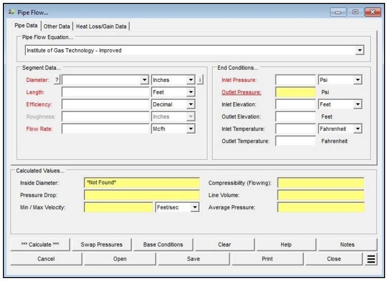
| Parameter | Description |
|---|---|
| Pipe Flow Equation | Specifies the flow equation to use during the calculation. Set to American Gas Association – Turbulent for this calculation. |
| Diameter | Specifies or displays the hydraulic (inside) diameter of the pipe segment. Click the ? command button to select a size using the Pipe Selection screen. May be designated the “unknown” value, in which case GASCalc sizes the pipe. |
| Length | Specifies or displays the hydraulic length of the pipe segment. |
| Efficiency | Specifies or displays the hydraulic efficiency value of the pipe segment (decimal fraction). |
| Roughness | Specifies the internal wall roughness of the pipe segment. Used only for certain flow equations; it is not used by the AGA – Turbulent equation, which uses a fixed roughness value (the field is disabled). |
| Flow Rate | Specifies or displays the flow rate through the pipe segment. Flow values represent “standard” volume, adjusted to the specified base pressure and temperature. |
| Inlet Pressure | Specifies or displays the pressure at the inlet (upstream) end of the pipe segment. Entered and displayed as gauge pressure. |
| Outlet Pressure | Specifies or displays the pressure at the outlet (downstream) end of the pipe segment. Entered and displayed as gauge pressure. |
| Inlet Elevation | Specifies the height above mean sea level at the inlet (upstream) end. Displayed only when the Atmospheric Pressure Method is not set to “None” or “None – Entered Value”. |
| Outlet Elevation | Specifies the height above mean sea level at the outlet (downstream) end. Displayed only when the Atmospheric Pressure Method is not set to “None” or “None – Entered Value”. |
| Inlet Atm Press | Specifies the atmospheric pressure value at the inlet (upstream) end. Displayed and enabled only when the Atmospheric Pressure Method is set to “None – Entered Value”. |
| Outlet Atm Press | Specifies the atmospheric pressure value at the outlet (downstream) end. Displayed and enabled only when the Atmospheric Pressure Method is set to “None – Entered Value”. |
| Inlet Temperature | Specifies the flowing temperature value at the inlet (upstream) end of the pipe segment. |
| Outlet Temperature | Specifies the flowing temperature value at the outlet (downstream) end. Calculated only when the Heat Loss/Gain method is not “None” or the Include Joule-Thomson Cooling option is selected. |
| Allowable Velocity | On the Other Data tab. Specifies the maximum allowable flow velocity used when calculating the hydraulic diameter. Enabled only when the Diameter value is “unknown”. |
| Compressibility Factor (Base / Flowing) | On the Other Data tab. Specifies the base and flowing compressibility factor values. Enabled only when the Compressibility Factor Method is set to “None – Entered Value”. |
| Pipe Material | On the Other Data tab. Specifies the pipe material used for the selected pipe sizes when calculating the diameter. Enabled only when the Diameter value is “unknown”. |
| Use A Single Pipe Size Only | On the Other Data tab. When selected, only one pipe size is considered during pipe selection. Enabled only when the Diameter value is “unknown”. |
| Ignore Components | On the Other Data tab. When selected, the equivalent length of attached components is not included in the calculation. |
| Additional Components | On the Other Data tab. A list of attached pipes and fittings that contribute equivalent length to the calculation. Managed with the Add, Insert, Delete, and Clear command buttons. |
| Base Conditions (Pressure / Temperature) | Set on the Base Conditions screen. Establishes the base (reference) pressure and temperature used for the calculation. |
| Atmospheric Pressure Method | Set on the Base Conditions screen. Determines how atmospheric pressure is established and controls whether the Elevation or Atm Press fields are displayed. |
| Compressibility Factor Method / Gas Properties File | Set on the Base Conditions screen. Selects the method for the compressibility factor and the gas composition file (or “None”) used in the calculation. |
Part 2: Outputs/Reports
- If you need to modify a data value, change it and click the CALCULATE button again. If the unknown (underlined) item is changed, re-select it before recalculating.
- Use the Swap Pressures command button to exchange the inlet and outlet conditions when working along several contiguous pipe sections.
- To SAVE the calculation, click the Save command button (calculation files use the .clc extension).
- To print the data values and results, click the Print command button and configure the Print Settings screen.
- To calculate a table of results over a range of values, use the Calculate Table Of Results Additional Action.
- To compare results by changing a value without re-entering all data, use the Open Duplicate Calculation Additional Action.
Results
| Output | Description |
|---|---|
| Unknown Value | The single item designated as “unknown” – for example, Outlet Pressure, Inlet Pressure, Flow Rate, Length, or Diameter – is solved for and reported in its field. |
| Inside Diameter | Displays the inside diameter of the pipe segment when a Size/Type Code is used to specify the Diameter value. |
| Pressure Drop | Displays the calculated linear pressure drop across the pipe segment, including all attached components. |
| Min / Max Velocity | Displays the calculated minimum and maximum flow velocity. The minimum is based on inlet (upstream) conditions; the maximum is based on outlet (downstream) conditions. |
| Compressibility (Flowing) | Displays the calculated average flowing compressibility factor, computed from the average pressure and temperature values. |
| Line Volume | Displays the calculated volume of the pipe segment, expressed with reference to the base conditions and computed from the average pressure, temperature, and compressibility values. Its dimensional units are based on the specified flow units. |
| Average Pressure | Displays the calculated average pressure along the pipe segment, used to compute the flowing compressibility and line volume. |
| Additional Length | Displays the total equivalent length of any attached fittings in the Additional Components list, added to the pipe length as required by the calculation. |
| Selected Pipe Sizes | Displays the selected pipe size or sizes and the associated lengths. Displayed only when the Diameter value is calculated. |
Note: Pressure values are entered and displayed in gauge units, and flow values represent “standard” volume adjusted to the base conditions. If the Limit Pipe Velocity To Sonic preference is enabled and the flow exceeds the segment’s sonic (choked) capacity at the specified conditions, the calculation is limited to the maximum choked flow value. The number of decimal places shown for any calculated item can be set under File > Preferences > Decimals.
References
- Industrial Press, Gas Engineers Handbook, 1965.
- American Gas Association, Gas Engineering and Operating Practices – System Design, GEOP Series Book D-1, 1990.
- Gas Processors Suppliers Association, Engineering Data Book, Eleventh Edition – FPS, 1998.
FAQ
-
Gas Purging Calculations?
Purging is a process of removing gas from the pipeline. Controlled purging of gases from pipelines by direct displacement with other gases that have been safely practiced for many years with the recognition that some flammable mixture is present. Purging of gases from pipelines by direct displacement with another gas also has been similarly practiced. It works both ways; however, there will always be an atmosphere of type of a mixture. This is due to the densities of the gases. Check Out
-
What is Erosional Velocity?
Pipe erosion begins when velocity exceeds the value of C/SQRT(ρ) in ft/s, where ρ = gas density (in lb./ft3) and C = empirical constant (in lb./s/ft2) (starting erosional velocity). We used C=100 as API RP 14E (1984). However, this value can be changed based on the internal conditions of the pipeline. Check Out
-
What is Sonic Velocity?
The maximum possible velocity of a compressible fluid in a pipe is called sonic velocity. Oilfield liquids are semi-compressible, due to dissolved gases. Check Out
-
What is Pipe Roughness?
Pipe roughness is a material property that refers to the absolute roughness of the internal pipe wall surface, used in friction factor calculations for pressure drop and flow calculations. These roughness values may be auto-populated by selecting the “Select Pipe Roughness” dropdown, or by manually inputting the value specified by the manufacturer.