
This article walks through three worked examples of attaching a background image to a new model — a bitmap (BMP) raster image, a DXF CAD drawing, and a shapefile (SHP) GIS file — each starting from a brand-new model and ending with the image displayed at the correct scale. Check and set the model’s Coordinate Values dimensional units before attaching or scaling any background image; getting this wrong is the most common cause of an image that looks the wrong size once attached.
Add A BMP Background Image
Attaches a bitmap (BMP) style background image to a new model and corrects its scale using two known points. Attaching a JPG or TIF image follows the same procedure.
- Create the new model: select New from the File menu, type a file name on the Save screen, and click Save. If the GDI Window doesn’t appear automatically, select View/Edit from the Graphics menu. Resize it with Maximize GDI Window from the GDI Utilities branch of the GDI Command Tree.
- Set the Coordinate Values units: select Options & Settings from the Utilities menu, and on the Units tab set Coordinate Values to Feet. Click Apply, then Close.
- Add the background image: select Background Settings from the Graphics menu, then click Attach New Image. On the Attachment File Type screen, choose BMP – Windows Bitmap Style Raster Or Image File and click Continue. Browse to the GASWorkS 11\files folder, select sample.bmp, and click Open. The default settings are fine for this example — click Apply to attach the image.
- Zoom to fit: click the Zoom To Fit icon in the lower-left corner of the GDI Window. If the image doesn’t appear, turn on Display Background Image from the Display Settings branch of the GDI Command Tree.
- Check the scale: select Zoom Window from the GDI View branch and draw a window around the reference square shown in the figure. Select Measure Distance from the GDI Utilities branch and measure between the two reference points. If the reported Absolute Distance doesn’t match the known field distance, the image needs rescaling.
- Adjust the scale: either open Background Settings and change the Scale Factor directly (if the measured distance is roughly double the actual distance, halve the Scale Factor), or select Scale Background Image from the GDI Command List, pick the same two reference points, and type in the actual known distance when prompted; respond Yes to apply the reported scale factor.
- Re-check the scale: click Zoom To Fit again, and re-measure the same reference distance to confirm it’s now correct. Repeat the previous step if it still isn’t.
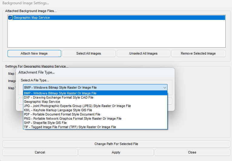
Notes
- GASWorkS can only display standard Windows bitmap files; convert scanned images or other raster output to BMP before attaching them.
- Bitmap images have a fixed resolution and lose quality when enlarged, especially in close-up sections — this is a normal property of bitmap images, not specific to GASWorkS.
- The scale of a BMP image is controlled by its Coordinate-To-Pixel Ratio — the real-world distance a single pixel represents. Change it directly as the Scale Factor on the Background Image Settings screen, or let Scale Background Image calculate it from two known points.
Add A DXF Background Image
Attaches a Drawing Exchange Format (DXF) style background image to a new model, checks its scale, and hides selected DXF layers to declutter the display.
- Create the new model: select New from the File menu, name and save it, and confirm the GDI Window is displayed (View/Edit on the Graphics menu if not). Resize it with Maximize GDI Window.
- Set the Coordinate Values units: on the Units tab of Options & Settings, set Coordinate Values to Feet. Click Apply, then Close.
- Add the background image: select Background Settings from the Graphics menu, click Attach New Image, choose DXF – Drawing Exchange Format Style CAD File, and click Continue. Browse to GASWorkS 11\files, select plat.dxf, and click Open. Click Apply to attach it with its default settings.
- Zoom to fit: click Zoom To Fit. If the image doesn’t appear, turn on Display Background Image from the Display Settings branch of the GDI Command Tree.
- Check the scale: select Zoom Window from the GDI View branch and window in on the reference square shown in the figure. Select Measure Distance from the GDI Utilities branch and measure between the two reference points shown; confirm the reported Absolute Distance is approximately correct.
- Zoom to fit again so the full background image fills the GDI Display.
- Turn some DXF layers off: reopen Background Settings, select the attached DXF file, and in the Layer Names list unselect the layers you want hidden (for example, right-of-way or text annotation layers). Click Apply.
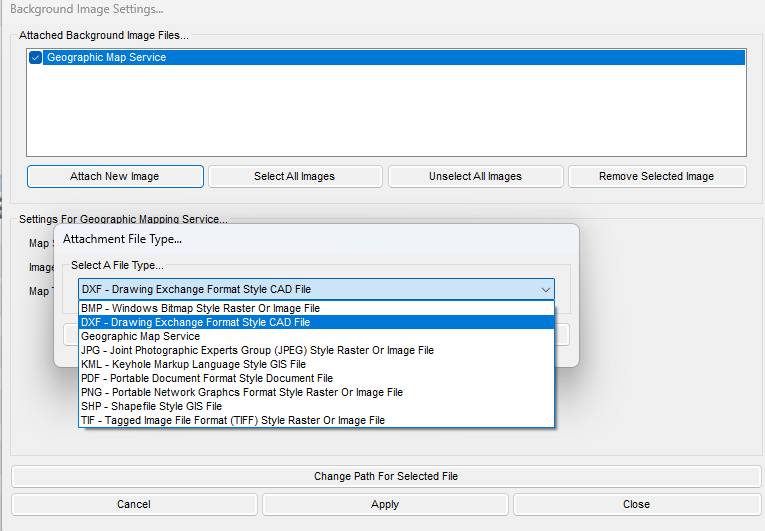
Like the BMP example, this is a multi-step tutorial rather than a single command — there is no GDI Command Line alias for “attaching a DXF image.”
Notes
- If more than one DXF file is attached, every file’s coordinates must be expressed in the same Coordinate Values dimensional units.
- A DXF image with a large number of features can slow the model’s screen refresh; turning off layers that contain irrelevant data helps declutter the display and improve performance.
- Unselect Convert Colors To Gray on the Background Image Settings screen to display the image in color instead of grayscale; choose a color not already used by model features to avoid confusion.
- The Scale Factor value sets the Drawing Unit-To-Coordinate Ratio; Scale Background Image can correct it directly in GASWorkS, but the recommended approach for DXF files is to rescale them in the original CAD program before attaching.
- A DXF file containing system piping data can be imported directly to build the piping schematic, rather than only attached as a background reference.
Add A SHP Background Image
Attaches a shapefile (SHP) style background image to a new model. Attaching a KML image follows the same procedure.
- Create the new model: select New from the File menu, name and save it, and confirm the GDI Window is displayed. Resize it with Maximize GDI Window.
- Set the Coordinate Values units: on the Units tab of Options & Settings, set Coordinate Values to Feet. Click Apply, then Close.
- Add the background image: select Background Settings from the Graphics menu, click Attach New Image, choose SHP – Shapefile Style GIS File, and click Continue. Browse to GASWorkS 11\files, select SHP_MAIN.shp, and click Open. Click Apply to attach it with its default settings.
- Zoom to fit: click Zoom To Fit. If the image doesn’t appear, turn on Display Background Image from the Display Settings branch of the GDI Command Tree.
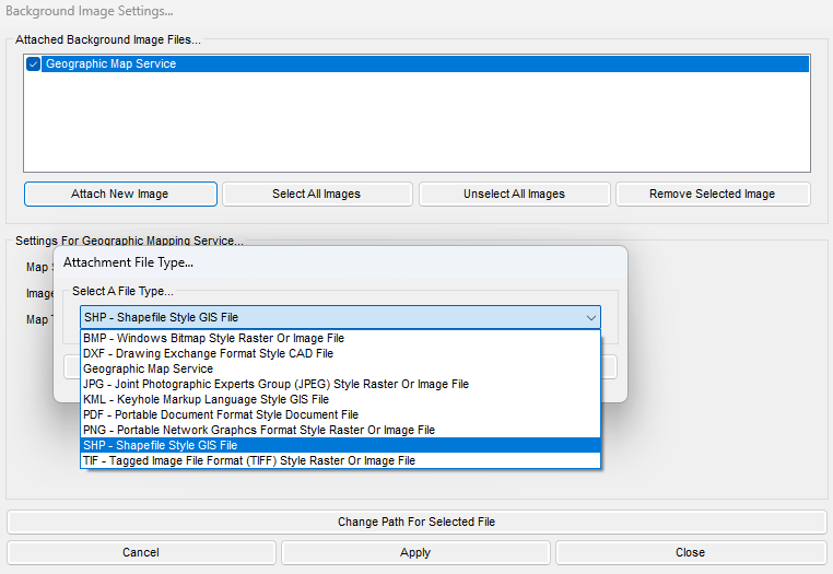
As with the other two examples, this is a multi-step tutorial rather than a single command — there is no GDI Command Line alias for “attaching a SHP image.”
Notes
- A SHP background image can be projected from latitude/longitude to a planar coordinate system such as State Plane by selecting Project To Model Coordinates on the Background Image Settings screen. If no projection file is associated with the model, GASWorkS will ask you to specify one.
- Unselect Convert Colors To Gray to display the image in color instead of grayscale; choose a color not already used by model features to avoid confusion.
- Line Weight and Line Style only apply to line-type SHP features; Point Symbol Size and Point Symbol Style only apply to point-type features.
- SHP files can contain arc (line), point, and polygon-type geographic features.
- The Scale Factor value sets the Drawing Unit-To-Coordinate Ratio; Scale Background Image can correct it directly if needed.
Notes & Considerations
- Set the model’s Coordinate Values dimensional units (Units tab, Options & Settings) before attaching or scaling any background image, regardless of file type.
- Multiple background images of different file types can be attached to the same model at once; GASWorkS supports BMP, DXF, JPG, KML, PDF, SHP, and TIF files as background images.
- The upper-left corner of an attached image is set by its Insertion Point (raster types) or Origin Shift (DXF/SHP) values, which default to (0,0) and can be changed on the Background Image Settings screen. The image can also be repositioned afterward with Move A Background Image — but establish the correct scale before setting its position.
- If Allow Undo Of Data/Graphic Changes is enabled (Utilities > Options & Settings > Environment), click the Undo icon to reverse the last data or graphic change.
See Also
- Display & Visibility Settings
- Example: Selecting, Moving & Viewing Features
- Views, Panning, Zooming & Plotting
- Measuring Distances & Angles
- Moving Text, Graphics, Legends & Views
- Importing CSV, DXF & KML Files
- Toggling Layers, Logs & GeoMapping
- Example: Importing DXF & Working with Shapefiles
FAQ
-
Which model file format should I choose when creating a new model?
For GASWorkS 11 we recommend the “.gwz” format, which stores the entire model as a single file. The older “hdr” format from GASWorkS 10.2 and earlier is still supported, but it stores the model as a group of individual files.
-
Do I have to set the default data values before I start building?We general advise to do so, because every new node and pipe is populated from the current default data values, allowing to avoid setting new values for every imported pipe. Additionally, default data values can be saved, allowing for new models to automatically use the same configuration. As an alternative, you can also select ‘Use Last Record As Default’ on the Default Data tab, which populates a new feature from the last similar feature already in the model.
-
What are the different ways to enter a node’s location?You can type an X-Y coordinate pair (for example, 1000,1000), enter a relative distance and angle prefixed with “@” (for example, @500<180, measured clockwise from north), or draw the segment with the mouse. You can also reference an existing node by name using the "N" prefix — typing "N SUPPLY" uses that node's location.
-
What does a negative load value mean?A negative load indicates gas leaving the system — a demand. Positive values, by contrast, represent gas entering the system.
-
My model has negative pressures after I added the new tap. What happened?Negative (below-zero) pressures mean the system has effectively “run out of gas” — the added demand is greater than the network’s capacity. To address this issue, we generally recommend using the color-coding feature (by Pipe Pressure Drop) to find the pipes with the highest drop, and resizing to a larger pipe where possible.
-
Why do I need to solve the model again after making a change?Any change to the model invalidates the previously computed pressures and flows, so you will need to re-solve to get valid results after you change an input. The Solve icon tells you the state of the calculator at a glance: the scale shows balanced (blue) after a successful solution and unbalanced when a change means a new solution is needed.
-
Can I export the report data to a spreadsheet?Yes. You can save the report directly as a Comma Separated Values (.csv) file and open it in a spreadsheet, or copy the report contents to the Windows Clipboard and paste them into another application. You can also use the Set Columns routine to choose which columns display and print, and build query-based selection sets to filter and sort the records.