
Introduction
The Bearing Capacity application checks that the soil or rock beneath each pipe support can carry the support reactions. It must have an adequate margin against bearing (shear) failure and excessive settlement. The reactions come from your Pipe Span & Support Analysis (Gas) case, using the governing (worst-case) load combination.
The application includes a footing simulation. It steps through combinations of footing length, width and depth and identifies the minimum footing size that passes for your span case, so you do not have to iterate by hand.
Support Types
- Pile-supported piers/bents: steel H-piles or pipe piles driven into the streambed or bank and capped with a saddle. Most common where the streambed is erodible, because the pile can be driven below the scour depth.
- Concrete piers/sleepers: spread footings on the streambed or bank, used where rock or dense soil is shallow and scour potential is low.
- Sled or skid supports: prefabricated steel supports set on the streambed, typically for temporary crossings or shallow, low-velocity channels.
- Existing structures: the pipe is carried by a bridge or similar structure; reactions are governed by the host structure’s design.
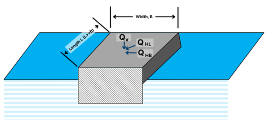
Calculation Methodology
Step 1: Ultimate Bearing Capacity (Shallow Foundations)
For spread footings, sleepers and sled supports, the ultimate bearing capacity uses the general bearing capacity equation (Terzaghi/Meyerhof form):
q_{ult}=c\,N_c\,s_c\,d_c+q\,N_q\,s_q\,d_q+0.5\,\gamma\,B\,N_\gamma\,s_\gamma\,d_\gammaWhere:
𝑐 − Soil Cohesion (psf)
𝑞 − Effective Overburden Pressure at Footing Depth (psf)
γ − Effective Unit Weight of Soil Below Footing (buoyant below the water table) (pcf)
𝐵 − Footing Width (ft)
Nc, Nq, Nγ − Bearing Capacity Factors (functions of friction angle φ)
sc, sq, sγ − Shape Factors
dc, dq, dγ − Depth Factors
The bearing capacity factors Nq and Nc are commonly calculated as shown below. Nγ depends on the method used (Meyerhof, Hansen or Vesić). [VERIFY]
N_q=e^{\pi\tan\phi}\tan^2\left(45^\circ+\frac{\phi}{2}\right),\quad N_c=(N_q-1)\cot\phiStep 2: Allowable and Applied Bearing Pressure
q_{allow}=\frac{q_{ult}}{FS}q_{applied}=\frac{R}{A}\le q_{allow}Where:
𝑅 − Support Reaction from the Span Case (lb)
𝐴 − Footing Bearing Area, L × B (ft2)
𝐹𝑆 − Factor of Safety
A minimum FS of 3.0 is typically used for sustained (dead + live) loads. A reduced FS of 2.0–2.25 may be used for short-duration wind or seismic cases, consistent with the operator’s geotechnical criteria.
Step 3: Footing Size Simulation
The simulation repeats Steps 1–2 for a range of footing sizes and reports which ones pass: [VERIFY]
- Set the range and increment for footing length (L), width (B) and depth (Df).
- For each size, the application calculates qult, qallow and qapplied.
- Each size is marked acceptable when qapplied ≤ qallow.
- The application reports the minimum acceptable length, width and depth.
- Increasing depth raises q (overburden) and the depth factors. Increasing width raises the γ term and the bearing area. Use the simulation to find the cheapest combination.
Pile Foundations
For pile-supported piers and bents, the ultimate pile capacity is shaft (skin friction) resistance plus end bearing:
Q_{ult}=Q_s+Q_p=f_s\,A_s+q_p\,A_pQ_{allow}=\frac{Q_{ult}}{FS},\quad R\le Q_{allow}Where:
fs − Unit Skin Friction (α-method for cohesive soils, β-method for cohesionless soils)
As − Pile Shaft Area in Contact with Soil
qp − Unit End Bearing Resistance
Ap − Pile Tip Area
A FS of 2.0–2.5 is typical for driven piles evaluated by static analysis. Higher values may apply where capacity is estimated rather than confirmed by load or dynamic testing (e.g., PDA/CAPWAP).
Case Guide
Part 1: Create Case
- Select the Bearing Capacity (Gas) application from the Design & Stress Analysis Module. [VERIFY]
- To create a new case, click the “Add Case” button.
- Enter Case Name, Location, Date and any necessary notes.
- Select the Pipe Span & Support Analysis case to take the support reactions from, or enter the reactions manually. [VERIFY]
- Fill out all required Parameters.
- Make sure the values you are inputting are in the correct units.
- Click the CALCULATE button to overview results.
Input Parameters [VERIFY]
- Vertical Support Reaction, QV (from span case)
- Horizontal Loads, QHL and QHB
- Soil Cohesion, c (psf)
- Soil Friction Angle, φ (°)
- Soil Unit Weight, γ (pcf)
- Depth to Water Table (ft)
- Design Scour Depth (ft)
- Factor of Safety, FS
- Footing Length, L (ft) – value or simulation range
- Footing Width, B (ft) – value or simulation range
- Footing Depth, Df (ft) – value or simulation range
- Simulation Increment

Part 2: Outputs/Reports
- If you need to modify an input parameter, click the CALCULATE button after the change.
- To SAVE, fill out all required case details then click the SAVE button.
- To rename an existing file, click the SAVE As button. Provide all case info then click SAVE.
- To generate a REPORT, click the REPORT button.
- The user may export the Case/Report by clicking the Export to Excel icon.
- To delete a case, click the DELETE icon near the top of the widget.
Results [VERIFY]
- Bearing Capacity Factors (Nc, Nq, Nγ)
- Shape and Depth Factors
- Ultimate Bearing Capacity, qult (psf)
- Allowable Bearing Pressure, qallow (psf)
- Applied Bearing Pressure, qapplied (psf)
- Pass/Fail Bearing Check
- Simulation Table of footing sizes with Pass/Fail
- Minimum Acceptable Footing Length, Width and Depth

References
- Terzaghi, K. – Theoretical Soil Mechanics
- Meyerhof, G.G. – Bearing Capacity of Foundations
- FHWA-HEC-18 – Evaluating Scour at Bridges
- ASME B31.8 – Gas Transmission and Distribution Piping Systems
- ASCE/SEI 7 – Minimum Design Loads and Associated Criteria for Buildings and Other Structures
FAQ
-
Restrained versus Unrestrained Pipe (Difference in Gas vs. Liquid)?
ASME B31.4 liquid and B31.8 gas codes include calculations for the net longitudinal compressive stress that must be applied only for a restrained line that equates to a low (less than 2%) longitudinal strain. This stress status is characteristic to underground pipelines located some distance away from above ground piping facilities.
Unrestrained lines means those above ground sections of piping without axial restraint as with buried pipe with soil. In others words the soil exerts substantial axial restraint, but not fully restrained. Check Out
-
What is the Maximum Span Length of rev1?
Regarding span factors with and without water are based on bending stress and deflection. Larger diameter pipe spans require saddles for stability. Many standards that require pipes to be filled with water are based on bending and shear stresses not to exceed 1,500 psi and a deflection between supports not exceed 0.1 inches. Check Out
-
What is the model used for Thrust at Blow-Off?