
This routine exports GASWorkS model data to a DXF (Drawing Exchange Format) file for use in CAD and graphics packages such as AutoCAD and Microstation. It is run from the Export item in the Utilities menu, and its progress is shown in the Export Log. The DXF Export Settings screen controls exactly which pipe, node, and customer features and annotations are written to the file — its four tabs (General, Pipe Items, Node Items, and Customer Items) are documented in detail below. This routine requires a model to be open with the GDI Window displayed before starting.
GDI Commands
Export A DXF File
Model data from GASWorkS can be exported to a DXF file.
- From the Utilities menu, select the Export item.
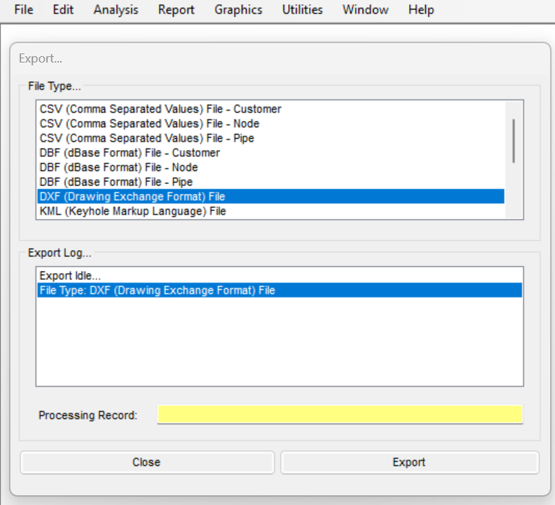
- The Export screen is displayed. Select the “DXF (Drawing Exchange Format) File” item from the File Type list. Click the Export button.
- The Save screen is displayed with a default File name and location. Either accept the default File name and location or change it. Click the Save button.
Note: If using an existing file, a message will be displayed asking whether to overwrite the file; respond appropriately. - The DXF Export Settings screen is displayed. Review the settings on the General, Pipe Items, Node Items, and Customer Items tabs (see below). When finished, click the Continue button.
- The Export screen is displayed again. The Export Log section will display the status of the Export routine. When the routine is complete, click the Close button.
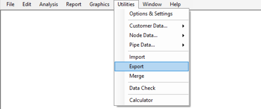
This routine is run by selecting the Export item from the Utilities menu and choosing the DXF file type; it has no GDI Command Line alias.
Notes
- The DXF Export routine creates a drawing exchange format (DXF) file. Once created, the DXF file can be imported or opened by CAD and graphics packages such as AutoCAD and Microstation.
- On the General tab of the DXF Export Settings screen is a Use Template File option. GASWorkS provides a default template file in the “GASWorkS 11\support\cad” folder. It is recommended to use this template file when exporting a DXF file for use in a CAD program, such as AutoCAD. However, a DXF file exported with this template cannot be imported back into GASWorkS.
DXF Export Settings
The DXF Export Settings screen determines what is written to the DXF file. It is organized into four tabs. The General tab sets file-wide options; the Pipe Items, Node Items, and Customer Items tabs each begin with a master “Include … Items” switch that turns that feature type on or off, followed by size and offset fields and a list of data items that can be annotated onto the exported features. Only the items whose boxes are checked are written to the file.
General Tab
The General tab sets file-wide options that apply to the whole export, including the optional CAD template file, the user graphic line-type scale, and which non-model elements (user graphics, user text, and dimensional units) are written to the file
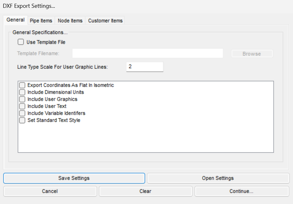
- Use Template File — Toggle use of a template DXF file. When checked, the Template Filename field and Browse button become active so a template can be selected.
- Template Filename — The path to the template DXF file to apply. Active only when Use Template File is checked; a default template is provided in the “GASWorkS 11\support\cad” folder.
- Line Type Scale For User Graphic Lines — Scale factor applied to the line-type (dash) pattern of exported user graphic lines.
- Export Coordinates As Flat In Isometric — Writes coordinates flattened rather than using an isometric projection.
- Include Dimensional Units — Writes the model’s dimensional units into the exported file.
- Include User Graphics — Includes user-drawn graphic entities in the export.
- Include User Text — Includes user-placed text entities in the export.
- Include Variable Identifers — Includes variable identifiers in the export.
- Set Standard Text Style — Applies a standard text style to the text written to the DXF file.
Pipe Items Tab
The Pipe Items tab controls whether pipes are exported and how they are drawn and annotated. Check Include Pipe Items to enable the tab, set the line, text, symbol, and flow-arrow sizes, then choose which pipe data items to annotate onto the exported pipes.
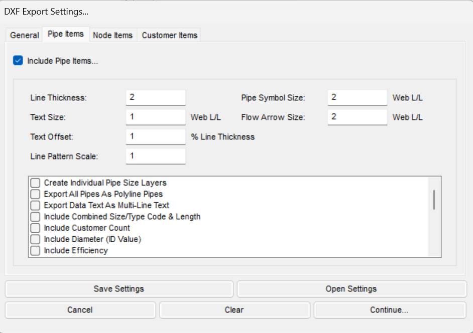
- Include Pipe Items — Master switch. When checked, pipe features are written to the DXF file and the settings below apply.
- Line Thickness — Thickness (weight) of the exported pipe lines.
- Text Size — Size of the pipe data text, in Web L/L units.
- Text Offset — Distance the text is offset from the pipe line, as a percentage of line thickness.
- Line Pattern Scale — Scale factor for the pipe line dash pattern.
- Pipe Symbol Size — Size of the exported pipe symbols, in Web L/L units.
- Flow Arrow Size — Size of the flow-direction arrows, in Web L/L units.
- Create Individual Pipe Size Layers — Places each pipe size on its own layer in the DXF file.
- Export All Pipes As Polyline Pipes — Exports every pipe as a polyline entity.
- Export Data Text As Multi-Line Text — Writes pipe data text as multi-line (MTEXT) rather than single-line text.
- Include Combined Size/Type Code & Length — Annotates each pipe with its combined size/type code and length.
- Include Customer Count — Annotates each pipe with the number of customers on it.
- Include Diameter (ID Value) — Annotates each pipe with its inside diameter (ID value).
- Include Efficiency — Annotates each pipe with its efficiency value.
- Include Flow Arrows — Draws flow-direction arrows on the pipes.
- Include Flow Rate — Annotates each pipe with its flow rate.
- Include Graphics — Includes the pipe graphic linework in the export.
- Include ID Number — Annotates each pipe with its ID number.
- Include Length — Annotates each pipe with its length.
- Include Link ID Number — Annotates each pipe with its link ID number.
- Include Pipe Symbols — Includes pipe symbols in the export.
- Include Pressure Drop — Annotates each pipe with its pressure drop.
- Include Roughness — Annotates each pipe with its roughness value.
- Include Size/Type Code — Annotates each pipe with its size/type code.
- Include Text For Pipe Elements Only — Limits text annotation to pipe elements only.
- Use Solid Symbols — Draws pipe symbols as solid (filled) rather than outline.
Node Items Tab
The Node Items tab controls whether nodes are exported and how they are drawn and annotated. Check Include Node Items to enable the tab, set the symbol and text sizes, then choose which node data items to annotate onto the exported nodes.
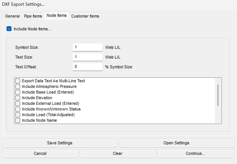
- Include Node Items — Master switch. When checked, node features are written to the DXF file and the settings below apply.
- Symbol Size — Size of the exported node symbols, in Web L/L units.
- Text Size — Size of the node data text, in Web L/L units.
- Text Offset — Distance the text is offset from the node symbol, as a percentage of symbol size.
- Export Data Text As Multi-Line Text — Writes node data text as multi-line (MTEXT) rather than single-line text.
- Include Atmospheric Pressure — Annotates each node with its atmospheric pressure.
- Include Base Load (Entered) — Annotates each node with its entered base load.
- Include Elevation — Annotates each node with its elevation.
- Include External Load (Entered) — Annotates each node with its entered external load.
- Include Known/Unknown Status — Annotates each node with the known/unknown status for pressure, base load, and temperature.
- Include Load (Total Adjusted) — Annotates each node with its total adjusted load.
- Include Node Name — Annotates each node with its name.
- Include Node Symbols — Includes node symbols in the export.
- Include Pressure — Annotates each node with its pressure.
- Include Temperature — Annotates each node with its temperature.
- Include Text Only For Nodes With Non-Zero Load Values — Writes node text only for nodes that have a non-zero load value.
Customer Items Tab
The Customer Items tab controls whether customers are exported and how they and their service lines are drawn and annotated. Check Include Customer Items to enable the tab, set the symbol, text, and service-line sizes, then choose which customer data items to annotate onto the exported customers.
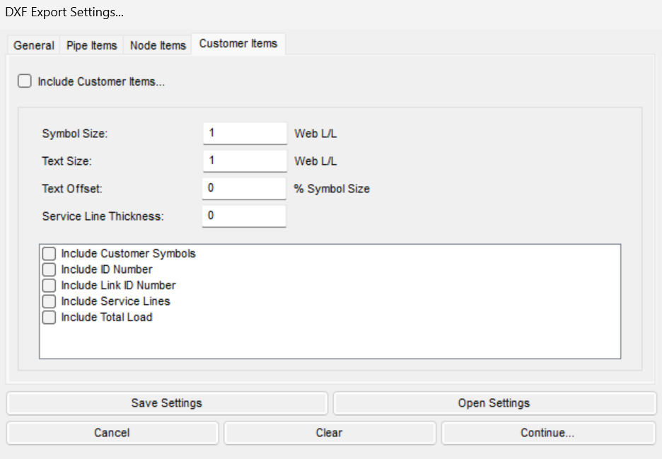
- Include Customer Items — Master switch. When checked, customer features are written to the DXF file and the settings below apply.
- Symbol Size — Size of the exported customer symbols, in Web L/L units.
- Text Size — Size of the customer data text, in Web L/L units.
- Text Offset — Distance the text is offset from the customer symbol, as a percentage of symbol size.
- Service Line Thickness — Thickness (weight) of the exported service lines.
- Include Customer Symbols — Includes customer symbols in the export.
- Include ID Number — Annotates each customer with its ID number.
- Include Link ID Number — Annotates each customer with its link ID number.
- Include Service Lines — Includes the customer service lines in the export.
- Include Total Load — Annotates each customer with its total load.
Notes & Considerations
- The routine assumes that GASWorkS has been started, a model is open, and the GDI Window is displayed.
- If an existing file is selected on the Save screen, a message will be displayed asking whether to overwrite the file; respond appropriately.
- Only the items whose boxes are checked on the DXF Export Settings screen are written to the file; the master “Include … Items” switch on the Pipe Items, Node Items, and Customer Items tabs turns that entire feature type on or off.
- The Export Log section of the Export screen displays the status of the routine; when the routine is complete, click the Close button.
See Also
- Exporting Model Data (CSV, DBF & XLS)
- Importing CSV, DXF & KML Files
- Example: Importing DXF & Working with Shapefiles
FAQ
-
Where do I start an export?From the Utilities menu, select the Export item, choose the desired File Type on the Export screen, and click the Export command button. Each routine then walks through a Save screen, a format-specific settings screen, and finally reports its status in the Export Log.
-
What coordinate system does a KML export require?The model must be in longitude and latitude coordinates to export a KML file. If it is not, a message may be displayed asking whether to project the coordinates before the export continues.
-
Can I control what ends up in a DXF export?Yes — the DXF Export Settings screen is displayed during the export so you can review the settings. Its General data tab includes a Use Template File option, and GASWorkS provides a default template in the “GASWorkS 11\support\cad” folder.