
Introduction
This application calculates the values associated with the flow of gas through a cone-style meter. A cone meter uses a cone-shaped element suspended in the meter tube; gas passes through the annular space around the cone, creating a measurable pressure drop that is used to determine the volumetric flow rate. The calculator can solve for flow rate, cone diameter, or differential pressure (whichever is designated as the “unknown”), and it reports the meter tube velocity and throat velocity as supporting results.
There are currently no industry standards covering the installation or flow calculation of cone meters; each manufacturer publishes its own method. Values such as the Meter Coefficient and Cone Diameter are unique to each meter and are taken from the manufacturer’s data sheet. The supported calculation methods are derived from manufacturer (McCrometer) literature, and the User must confirm that the selected method is appropriate for the device being analyzed.
Background
Various methods and devices are used to measure the flow of gas at a specific location; these devices are generally referred to as “meters.” A cone meter relies on the known characteristics of gas flowing around a cone-shaped object inserted in a meter tube. The geometry forces the gas to pass through the annular area between the tube wall and the cone, producing a pressure differential that can be measured and related to a volumetric flow rate. Because no specific industry standard governs these devices, the installation details and calculation procedures are supplied by each manufacturer.
Diameter Temperature Compensation
The cone and tube diameters are physical dimensions established at a known reference temperature. When the gas flows at a temperature different from that reference, the metal expands or contracts, changing the effective dimensions. GASCalc adjusts both the cone diameter and the tube diameter for this thermal effect before computing the flow.
Throat and Tube Velocity
The meter tube/pipe velocity is the velocity of the flow through the specified tube diameter, evaluated at the static pressure and unadjusted for flowing temperature. The throat velocity is the velocity of the flow stream through the annular space between the tube and the cone, also evaluated at the static pressure and unadjusted for flowing temperature; this value is approximate. If the throat velocity exceeds the Normal Velocity Limit set in the Check Limits preferences, the value is displayed in red text to flag a possible issue.
Equations
The calculator provides several methods for calculating the parameters associated with a cone meter. Each method is unique and may have specific limitations, so the User must determine the appropriate equation for the application being analyzed. The supported equations are described below.
Diameter Temperature Compensation
The tube and cone diameter values are adjusted to compensate for expansion and contraction caused by differences between the reference temperature and the flowing temperature, using the following equations (derived from Reference 1):
\begin{aligned} d &= d_R \times (1 + \alpha \times (T_F - T_R)) \\ D &= D_R \times (1 + \alpha \times (T_F - T_R)) \end{aligned}\begin{aligned} d &= d_R \times (1 + \alpha \times (T_F – T_R)) \\ D &= D_R \times (1 + \alpha \times (T_F – T_R)) \end{aligned}
Where:
d − Meter Cone Outside Diameter (feet)
dR − Meter Cone Diameter at the Reference Temperature (feet)
D − Meter Tube Inside Diameter (feet)
DR − Meter Tube Diameter at the Reference Temperature (feet)
TF − Temperature at Flowing (Metered) Conditions (°R)
TR − Reference Temperature for Meter Tube and Cone Dimensions (°R)
Standard Volumetric Flow Rate
The flow computed at flowing conditions is converted to the specified base (standard) conditions using the following equation (derived from Reference 2):
Q_B = Q_F \times \left[\frac{P_F}{P_B}\right] \times \left[\frac{T_B}{T_F}\right] \times \left[\frac{Z_B}{Z_F}\right] \times MFQ_B = Q_F \times \left[\frac{P_F}{P_B}\right] \times \left[\frac{T_B}{T_F}\right] \times \left[\frac{Z_B}{Z_F}\right] \times MF
Where:
QB − Metered Volume at the Specified Base Pressure and Temperature (ft3)
QF − Metered Volume at Flowing (Metered) Conditions (ft3)
PF − Pressure at Flowing (Metered) Conditions (psia)
PB − Base Pressure (psia)
TB − Base Temperature (°R)
TF − Temperature at Flowing (Metered) Conditions (°R)
ZB − Compressibility Factor at Specified Base Conditions
ZF − Compressibility Factor at Flowing (Metered) Conditions
MF − Meter Adjustment Factor
McCrometer Methods
This method calculates the volumetric flow through the meter at flowing conditions using the following equations (derived from References 1 and 3). The flow rate is governed by the equation constant, the gas expansion factor, the differential pressure, and the flowing density:
Q_F = K_1 \times Y \times \left[\frac{DP}{\rho_F}\right]^{0.5}Q_F = K_1 \times Y \times \left[\frac{DP}{\rho_F}\right]^{0.5}
Where:
QF − Metered Volume at Flowing (Metered) Conditions (ft3)
K1 − Equation Constant
Y − Expansion Factor
DP − Pressure Differential at Flowing (Metered) Conditions (psia)
The equation constant combines the meter geometry and the meter coefficient:
K_1 = \frac{\pi}{4} \times (2g)^{0.5} \times \left[\frac{D^2 \times \beta^2}{(1 - \beta^4)^{0.5}}\right] \times C_DK_1 = \frac{\pi}{4} \times (2g)^{0.5} \times \left[\frac{D^2 \times \beta^2}{(1 – \beta^4)^{0.5}}\right] \times C_D
Where:
K1 − Equation Constant
g − Gravitational Constant (ft/sec2)
D − Meter Tube Inside Diameter (feet)
CD − Meter Coefficient (dimensionless)
The beta ratio relates the cone and tube diameters:
\beta = \left[1 - \frac{d^2}{D^2}\right]^{0.5}\beta = \left[1 – \frac{d^2}{D^2}\right]^{0.5}
Where:
d − Meter Cone Outside Diameter (feet)
D − Meter Tube Inside Diameter (feet)
The gas density at flowing conditions is determined from the specific gravity, flowing pressure, flowing temperature, and compressibility:
\rho_F = 2.6988 \times SG \times \frac{P_F}{Z_F \times T_F}\rho_F = 2.6988 \times SG \times \frac{P_F}{Z_F \times T_F}
Where:
SG − Ideal Gas Specific Gravity
PF − Pressure at Flowing (Metered) Conditions (psia)
ZF − Compressibility Factor at Flowing (Metered) Conditions
TF − Temperature at Flowing (Metered) Conditions (°R)
Expansion Factor — Adiabatic Expansion Method
For the Adiabatic Expansion Method, the expansion factor is calculated as follows:
Y = \left[\frac{(1 - \beta^4) \times \dfrac{k}{k-1} \times R^{\frac{2}{k}} \times \left(1 - R^{\frac{k-1}{k}}\right)}{\left[1 - \beta^4 \times R^{\frac{2}{k}}\right] \times (1 - R)}\right]^{0.5} \qquad R = 1 - \frac{DP}{P_F}Y = \left[\frac{(1 – \beta^4) \times \dfrac{k}{k-1} \times R^{\frac{2}{k}} \times \left(1 – R^{\frac{k-1}{k}}\right)}{\left[1 – \beta^4 \times R^{\frac{2}{k}}\right] \times (1 – R)}\right]^{0.5} \qquad R = 1 – \frac{DP}{P_F}
Where:
Y − Expansion Factor
k − Ratio of Specific Heats
R − Pressure Ratio
DP − Pressure Differential at Flowing (Metered) Conditions (psia)
PF − Pressure at Flowing (Metered) Conditions (psia)
Expansion Factor — V-Cone Method
For the V-Cone Method, the expansion factor is calculated as follows:
Y = 1 - \left[(0.649 + 0.696\beta^4) \times \frac{DP}{k \times P_F}\right]Y = 1 – \left[(0.649 + 0.696\beta^4) \times \frac{DP}{k \times P_F}\right]
Where:
Y − Expansion Factor
DP − Pressure Differential at Flowing (Metered) Conditions (psia)
k − Ratio of Specific Heats
PF − Pressure at Flowing (Metered) Conditions (psia)
Expansion Factor — Wafer-Cone Method
For the Wafer-Cone Method, the expansion factor is calculated as follows:
Y = 1 - \left[(0.755 + 6.787\beta^8) \times \frac{DP}{k \times P_F}\right]Y = 1 – \left[(0.755 + 6.787\beta^8) \times \frac{DP}{k \times P_F}\right]
Where:
Y − Expansion Factor
DP − Pressure Differential at Flowing (Metered) Conditions (psia)
k − Ratio of Specific Heats
PF − Pressure at Flowing (Metered) Conditions (psia)
The flowing pressure is the sum of the gauge pressure and the atmospheric pressure: PF = PFG + PATM, where PFG is the gauge pressure at flowing conditions (psig) and PATM is the atmospheric pressure at the metered location (psia). Unless otherwise noted, all values are in consistent dimensional units.
Case Guide
Part 1: Create Case
- Select the Cone Meter application from the Meters Module. The Cone Meter Values calculation screen will be displayed.
- Click the Clear command button to set all values to an empty (null) value.
- Click the Base Conditions command button, enter an appropriate base pressure and temperature, select a Gas Properties File (or “None” and enter the gas properties manually), select an Atmospheric Pressure Method and a Compressibility Factor Method, then click Apply.
- From the Calculation Method list, select an appropriate method.
- Click on the red label associated with the item to be calculated (the “unknown” value) until the label is underlined; only one red item may be selected.
- Select the desired dimensional units for all data items and enter a value for all known data items.
- For the cone and tube Expansion Factors, click the ? command button next to each label and select the appropriate material from the Coefficient Of Linear Thermal Expansion screen, then click Apply.
- Click the CALCULATE command button to overview results.
Input Parameters
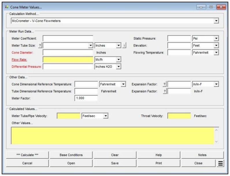
| Parameter | Description |
|---|---|
| Calculation Method | Specifies which method is used to perform the calculation (e.g., McCrometer – V-Cone Flowmeters). |
| Meter Coefficient | Specifies the flow/sizing coefficient for the associated meter. This value is unique to each meter and is generally found on the manufacturer’s data sheet. |
| Meter Tube Size | Specifies the inside diameter of the meter tube in which the meter is installed. Click the ? command button to select a size using the Pipe Selection screen; the corresponding inside diameter is read from the Pipe Property Table. |
| Cone Diameter | Specifies or displays the cone/orifice diameter value. This value is unique to each meter and is generally found on the manufacturer’s data sheet. May be designated as the “unknown” to solve for. |
| Flow Rate | Specifies or displays the volumetric flow rate through the meter. May be designated as the “unknown” to solve for. |
| Differential Pressure | Specifies or displays the pressure differential across the meter. May be designated as the “unknown” to solve for. |
| Static Pressure | Specifies the static pressure upstream of the meter cone. |
| Elevation | Specifies the height above mean sea level at the location of the cone meter. Only displayed when the Atmospheric Pressure Method in the Base Conditions is not set to “None” or “None – Entered Value”. |
| Atm Pressure | Specifies the atmospheric pressure value at the location of the cone meter. Only displayed when the Atmospheric Pressure Method in the Base Conditions is set to “None – Entered Value”. |
| Flowing Temperature | Specifies the temperature of the gas flowing through the meter. |
| Cone Dimensional Reference Temperature | Specifies the reference temperature for the diameter value of the cone/orifice. |
| Tube Dimensional Reference Temperature | Specifies the reference temperature for the diameter value of the meter tube. Not used by all calculation methods. |
| Expansion Factor (Cone & Tube) | Specifies the coefficient of linear thermal expansion factor for the cone and/or meter tube material. Click the ? command button to select a value using the Coefficient Of Linear Thermal Expansion screen. |
| Meter Factor | Specifies an “adjustment” factor for the meter. A value greater than 1.0 increases the flow rate, less than 1.0 reduces it, and 1.0 leaves it unchanged. Used to match calculated flow to field-determined results. |
| Compressibility Factor (Base / Flowing) | Specifies the compressibility factor for the base and flowing conditions. Only displayed when the Compressibility Factor Method in the Base Conditions is set to “None – Entered Values”. |
| Base Pressure / Base Temperature | Set on the Base Conditions screen. Establishes the base (reference) pressure and temperature used to report the standard volumetric flow rate. |
| Atmospheric Pressure Method | Set on the Base Conditions screen. Determines how atmospheric pressure is established and controls whether the Elevation or Atm Pressure field is displayed. |
| Compressibility Factor Method | Set on the Base Conditions screen. Selects the method used to determine the base and flowing compressibility factors; requires an associated Gas Properties File when set to a method other than “None”. |
Part 2: Outputs/Reports
- If you need to modify an input parameter, click the CALCULATE button after the change.
- Review the calculated Flow Rate (if designated unknown), the Meter Tube/Pipe Velocity, the Throat Velocity, and any method-specific intermediate results shown in the Other Values panel.
- To SAVE the calculation, click the Save command button (calculation files use the .vcm extension).
- To print the data values and results, click the Print command button and configure the Print Settings screen.
- To calculate a table of results over a range of values, use the Calculate Table Of Results Additional Action.
- To compare results by changing a value without re-entering all data, use the Open Duplicate Calculation Additional Action.
Results
| Output | Description |
|---|---|
| Flow Rate | Displays the calculated volumetric flow rate through the meter, reported at the specified base conditions (when Flow Rate is designated the unknown value). |
| Meter Tube/Pipe Velocity | Displays the calculated velocity of the flow through the upstream meter tube, based on the specified tube diameter and static pressure, unadjusted for flowing temperature. |
| Throat Velocity | Displays the approximate velocity of the flow stream through the annular space around the cone, based on the static pressure and unadjusted for flowing temperature. Shown in red text if it exceeds the Normal Velocity Limit set in the Check Limits preferences. |
| Other Values | Displays additional method-specific intermediate results. The contents vary with the selected calculation method and may be used to verify or compare results against other procedures or published example calculations. |
Note: Depending on the number of decimal places displayed in your software, calculated values may not appear exactly as in published examples; results should match when rounded to the least common decimal place. The number of decimal places shown for any calculated item can be set under File > Preferences > Decimals.
References
- McCrometer, Flow Calculations For The V-Cone and Wafer-Cone Flowmeters, Lit #24509-54, Rev 3.2, 2008.
- American Gas Association, Measurement, GEOP Series Book M-1, 1993.
- McCrometer, Advanced Differential Pressure Flow Technology, Article ARTC02031710, 2002.
FAQ
-
What information do I need before running a meter calculation?
You will need the meter size/type code (selectable from the built-in meter table), the known value for either inlet pressure or flow rate, the flowing temperature, elevation or atmospheric pressure at the meter location, and base conditions including base pressure and temperature. Gas properties — particularly specific gravity — are also required, either entered manually or loaded from a gas properties file. If compressibility corrections are needed, a compressibility factor method must also be selected in Base Conditions.
-
What is the Rated Capacity Adjustment Factor and how should I interpret it?The Rated Capacity Adjustment Factor is the ratio of the meter’s actual flowing capacity (at the specified operating conditions) to its nameplate rated capacity. A factor greater than 1.0 indicates the meter can handle more standard volume flow than its nameplate rating under the given conditions — typically because the operating pressure is higher than the rated pressure. The factor is useful for confirming that a given meter size can handle the required flow at the intended operating pressure
-
Are there any limitations or assumptions in the calculation I should be aware of?Yes. GASCalc assumes the compressibility factor at rated base conditions (Z_BR) equals 1.0 and that the rated temperature (T_R) is 60 °F. The calculator does not predict rotor speed or enforce manufacturer speed limits — exceeding the meter’s maximum rated speed can cause immediate or premature mechanical failure, so results must be checked against the manufacturer’s specifications. Additionally, there is no common consensus standard for meter sizing, so this method may differ from the approach used by a specific meter manufacturer.
-
When should I use the Meter Values calculator versus the Meter MatchMaker?Use the Meter MatchMaker when you have not yet selected a meter and need to identify which size and type best fits a given application. Once a specific meter model has been chosen, use that meter’s Values calculator to confirm or compute the flow rate or inlet pressure at defined operating conditions and to determine the Rated Capacity Adjustment Factor.