
Introduction
The Diaphragm Meter calculator computes the flow capacity of a diaphragm meter operating at conditions that differ from its factory-rated pressure and differential. Given the meter type, inlet pressure, differential pressure, flowing temperature, and gas properties, it calculates the actual flow rate through the meter along with a Rated Capacity Adjustment Factor. Three industry-standard sizing methods are supported: Rockwell, GRI/SWRI, and Sprague.
Important: There is no single consensus standard for diaphragm meter sizing. The three methods supported by the calculator are intended for determining design capacity, not for computing the actual gas flow through a meter at precise operating conditions. The user must select the method appropriate for the application being analyzed. The Rockwell and GRI/SWRI methods are mathematically equivalent but are drawn from different source references.
Background
A diaphragm meter is a type of positive displacement meter. It measures gas flow by counting the number of times gas fills and empties a chamber of known volume. Manufacturers rate diaphragm meters at a specific inlet pressure and differential pressure — for example, 250 cfh at 7 inches H₂O inlet pressure and 0.5 inches H₂O differential. In practice, meters are often operated under conditions that differ from these rated values, and it is common industry practice to use a meter when actual flow exceeds its nameplate rating.
Two physical parameters control how much gas a diaphragm meter can pass:
Effect of Inlet Pressure
Because gas is compressible, increasing the operating pressure of the meter increases the mass of gas contained in the reference chamber during each fill-and-empty cycle. A higher-pressure meter therefore passes more standard cubic feet per cycle than the same meter at a lower pressure, effectively increasing its rated capacity.
Effect of Differential Pressure
The differential pressure across the meter governs how quickly the reference chamber is cycled. Increasing the differential increases the cycle rate, which increases the volume of gas metered over any given time period — again raising effective capacity. However, operating at elevated differential subjects the meter’s mechanical components to more cycles per unit time. This accelerates wear and can shorten the meter’s service life. There is also a physical ceiling on how fast the mechanical components can operate; exceeding it risks meter failure or inaccuracy.
Sizing Considerations
When selecting a diaphragm meter for a new installation, the sizing load should reflect the maximum flow the meter will practically encounter. For installations with many gas-using appliances, the total connected load is often derated to account for diversity — the fact that not all appliances operate simultaneously at full capacity. The derated load is then used to determine the required meter capacity.
Equations
All three methods share the same general structure: the meter’s rated capacity is first adjusted to the specified base conditions, then adjusted further to account for actual flowing pressure, differential pressure, specific gravity, temperature, and compressibility.
Rockwell Diaphragm Meter Sizing
The Rockwell method calculates the meter capacity at flowing conditions as:
Q_F = Q_R \times \left[\frac{P_F}{P_R}\right]^{0.5} \times \left[\frac{DP_F - DP_{FRICTION}}{DP_R - DP_{FRICTION}}\right]^{0.5} \times \left[\frac{SG_R}{SG}\right]^{0.5} \times \left[\frac{T_R}{T_F}\right]^{0.5} \times \left[\frac{Z_R}{Z_F}\right]^{0.5}Q_F = Q_R \times \left[\frac{P_F}{P_R}\right]^{0.5} \times \left[\frac{DP_F – DP_{FRICTION}}{DP_R – DP_{FRICTION}}\right]^{0.5} \times \left[\frac{SG_R}{SG}\right]^{0.5} \times \left[\frac{T_R}{T_F}\right]^{0.5} \times \left[\frac{Z_R}{Z_F}\right]^{0.5}
Where:
QF − Meter capacity at flowing (metered) conditions (ft3)
QR − Meter rated capacity converted to the specified base pressure and temperature (ft3)
PF − Pressure at flowing (metered) conditions (psia); PF = PFG + PATM
PR − Pressure at rated conditions (psia); PR = PRG + PR,ATM
DPF − Differential pressure at flowing (meter) conditions (inches H₂O)
DPFRICTION − Known or published frictional pressure loss for the meter (inches H₂O)
DPR − Differential pressure at rated conditions (inches H₂O)
SGR − Specific gravity at rated conditions (dimensionless)
SG − Specific gravity of flowing (metered) gas (dimensionless)
TR − Temperature at rated conditions (Rankine); assumed to be 60 °F
TF − Temperature at flowing (metered) conditions (Rankine)
ZR − Compressibility factor at rated conditions (dimensionless)
ZF − Compressibility factor at flowing (metered) conditions (dimensionless)
When the rated capacity adjusted to the specified base conditions the equation is:
Q_R = Q_{RATED} \times \left[\frac{P_{BR}}{P_B}\right] \times \left[\frac{T_B}{T_{BR}}\right] \times \left[\frac{Z_B}{Z_{BR}}\right]Q_R = Q_{RATED} \times \left[\frac{P_{BR}}{P_B}\right] \times \left[\frac{T_B}{T_{BR}}\right] \times \left[\frac{Z_B}{Z_{BR}}\right]
Where:
QR − Meter rated capacity converted to the specified base pressure and temperature (ft3)
QRATED − Meter capacity at rated base pressure and temperature (ft3)
PBR − Base pressure at rated conditions (psia)
PB − Base pressure (psia)
TB − Base temperature (Rankine)
TBR − Base temperature at rated conditions (Rankine)
ZB − Compressibility factor at specified base conditions (dimensionless)
ZBR − Compressibility factor at rated base conditions (dimensionless); assumed to be 1.0
GRI/SWRI Diaphragm Meter Sizing
The GRI/SWRI method uses the same equations as the Rockwell method but is derived from different source references (References 1 and 4 vs. References 1 and 3):
Q_F = Q_R \times \left[\frac{P_F}{P_R}\right]^{0.5} \times \left[\frac{DP_F - DP_{FRICTION}}{DP_R - DP_{FRICTION}}\right]^{0.5} \times \left[\frac{SG_R}{SG}\right]^{0.5} \times \left[\frac{T_R}{T_F}\right]^{0.5} \times \left[\frac{Z_R}{Z_F}\right]^{0.5}Q_F = Q_R \times \left[\frac{P_F}{P_R}\right]^{0.5} \times \left[\frac{DP_F – DP_{FRICTION}}{DP_R – DP_{FRICTION}}\right]^{0.5} \times \left[\frac{SG_R}{SG}\right]^{0.5} \times \left[\frac{T_R}{T_F}\right]^{0.5} \times \left[\frac{Z_R}{Z_F}\right]^{0.5}
Where:
QF − Meter capacity at flowing (metered) conditions (ft3)
QR − Meter rated capacity converted to the specified base pressure and temperature (ft3), computed using the base-condition adjustment shown under the Rockwell method
PF − Pressure at flowing (metered) conditions (psia); PF = PFG + PATM
PR − Pressure at rated conditions (psia); PR = PRG + PR,ATM
DPF − Differential pressure at flowing (meter) conditions (inches H₂O)
DPFRICTION − Known or published frictional pressure loss for the meter (inches H₂O)
DPR − Differential pressure at rated conditions (inches H₂O)
SGR − Specific gravity at rated conditions (dimensionless)
SG − Specific gravity of flowing (metered) gas (dimensionless)
TR − Temperature at rated conditions (Rankine); assumed to be 60 °F
TF − Temperature at flowing (metered) conditions (Rankine)
ZR − Compressibility factor at rated conditions (dimensionless)
ZF − Compressibility factor at flowing (metered) conditions (dimensionless)
Sprague Diaphragm Meter Sizing
The Sprague method modifies the pressure ratio exponent from 0.5 to 0.75, reflecting a different empirical model for how inlet pressure affects capacity:
Q_F = Q_R \times \left[\frac{P_F}{P_R}\right]^{0.75} \times \left[\frac{DP_F - DP_{FRICTION}}{DP_R - DP_{FRICTION}}\right]^{0.5} \times \left[\frac{SG_R}{SG}\right]^{0.5} \times \left[\frac{T_R}{T_F}\right]^{0.5} \times \left[\frac{Z_R}{Z_F}\right]^{0.5}Q_F = Q_R \times \left[\frac{P_F}{P_R}\right]^{0.75} \times \left[\frac{DP_F – DP_{FRICTION}}{DP_R – DP_{FRICTION}}\right]^{0.5} \times \left[\frac{SG_R}{SG}\right]^{0.5} \times \left[\frac{T_R}{T_F}\right]^{0.5} \times \left[\frac{Z_R}{Z_F}\right]^{0.5}
Where:
QF − Meter capacity at flowing (metered) conditions (ft3)
QR − Meter rated capacity converted to the specified base pressure and temperature (ft3); the base-condition adjustment is identical to the Rockwell and GRI/SWRI methods
PF − Pressure at flowing (metered) conditions (psia); PF = PFG + PATM
PR − Pressure at rated conditions (psia); PR = PRG + PR,ATM
DPF − Differential pressure at flowing (meter) conditions (inches H₂O)
DPFRICTION − Known or published frictional pressure loss for the meter (inches H₂O)
DPR − Differential pressure at rated conditions (inches H₂O)
SGR − Specific gravity at rated conditions (dimensionless)
SG − Specific gravity of flowing (metered) gas (dimensionless)
TR − Temperature at rated conditions (Rankine); assumed to be 60 °F
TF − Temperature at flowing (metered) conditions (Rankine)
ZR − Compressibility factor at rated conditions (dimensionless)
ZF − Compressibility factor at flowing (metered) conditions (dimensionless)
Rated Capacity Adjustment Factor
The Rated Capacity Adjustment Factor is the ratio of the computed flowing capacity to the meter’s nameplate-rated capacity:
FACTOR = \frac{Q_F}{Q_{RATED}}FACTOR = \frac{Q_F}{Q_{RATED}}
Where:
FACTOR − Rated capacity adjustment factor (dimensionless)
QF − Meter capacity at flowing (metered) conditions (ft3)
QRATED − Meter capacity at rated base pressure and temperature (ft3)
Case Guide
Part 1: Create Case
- Select the Diaphragm Meter application from the Meters Module.
- From the Meters menu, select the Diaphragm Meter item. The Diaphragm Meter Values calculation screen will be displayed.
- Click the Clear button to set all values to blank (null).
- Click the Base Conditions button. Enter the appropriate base pressure and temperature, select or enter gas property values, choose the Atmospheric Pressure Method, and select the Compressibility Factor Method. Click Apply to save and return.
- From the Calculation Method list, select the desired sizing method: Rockwell Diaphragm Meter Sizing, GRI/SWRI Diaphragm Meter Sizing, or Sprague Diaphragm Meter Sizing.
- In the Meter Data section, click the red label of the item to be calculated (Flow Rate, Inlet Pressure, or Differential Pressure) until it is underlined.
- Click the ? button next to Meter Size/Type to open the Meter Selection screen and choose the appropriate diaphragm meter.
- Enter all known values: Inlet Pressure, Differential Pressure, Elevation, and Flowing Temperature. Select appropriate dimensional units for each field.
- Click the Calculate button to compute results.
Input Parameters
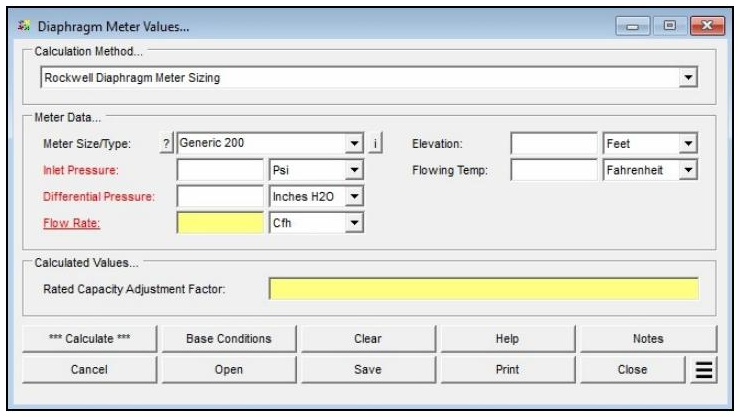
| Parameter | Description |
|---|---|
| Calculation Method | Specifies which method is used to perform the calculation: Rockwell Diaphragm Meter Sizing, GRI/SWRI Diaphragm Meter Sizing, or Sprague Diaphragm Meter Sizing. |
| Meter Size/Type | Specifies the meter Size/Type Code. Click the ? command button to select a meter using the Meter Selection screen. |
| Inlet Pressure | Specifies or displays the pressure at the inlet (upstream) side of the meter. |
| Differential Pressure | Specifies or displays the pressure differential across the meter. |
| Flow Rate | Specifies or displays the flow rate through the meter. Click the red label to select this as the unknown to be solved. |
| Elevation | Specifies the height above mean sea level at the location of the meter. Displayed when the Atmospheric Pressure Method in Base Conditions is not set to “None” or “None – Entered Value.” |
| Flowing Temp | Specifies the temperature of the gas flowing through the meter. |
| Atm Pressure | Specifies the atmospheric pressure at the meter location. Displayed only when the Atmospheric Pressure Method in Base Conditions is set to “None – Entered Value.” |
| Compressibility Factor (Base) | Specifies the compressibility factor for the specified base conditions. Displayed only when the Compressibility Factor Method in Base Conditions is set to “None – Entered Values.” |
| Compressibility Factor (Flowing) | Specifies the compressibility factor for the specified flowing conditions. Displayed only when the Compressibility Factor Method in Base Conditions is set to “None – Entered Values.” |
Part 2: Outputs/Reports
- If you need to modify an input parameter, update the value and click the CALCULATE button again.
- To SAVE, click the Save command button. Provide a file name and location (.dpm file).
- To open a previously saved calculation, click the Open command button and select the .dpm file.
- To generate a REPORT, click the Print command button to access the Print Settings screen.
- To calculate results across a range of values (e.g. a range of inlet pressures), use Additional Actions > Calculate Table of Results.
- To compare results for different meter types or methods, use Additional Actions > Open Duplicate Calculation.
- To add a title or notes to the calculation, click the Notes command button.
Results
| Output | Description |
|---|---|
| Inlet Pressure | The pressure at the inlet (upstream) side of the meter. Displayed when selected as the unknown to be solved (cfh or m³/h). |
| Differential Pressure | The pressure differential across the meter. Displayed when selected as the unknown to be solved (inches H₂O or millibar). |
| Flow Rate | The meter capacity at the specified flowing conditions. Displayed when selected as the unknown to be solved (cfh or m³/h). |
| Rated Capacity Adjustment Factor | The ratio of the computed flowing capacity to the meter’s nameplate-rated capacity (dimensionless). A value greater than 1.0 means the meter can pass more flow than its nameplate rating under the specified conditions. |
References
- American Gas Association — Measurement, GEOP Series Book M-1, 1993.
- Howard W. Berhegger, Sprague Meter Division of Textron — “Diaphragm Meter Capacity Ratings At Elevated Pressures,” paper presented at the 55th International School of Hydrocarbon Measurement, 1980.
- H.J. Evans, Rockwell Manufacturing Company — “Effect Of High Differential On Diaphragm Meter Accuracy,” proceedings of the Twenty-Ninth Annual Gas Measurement Short Course.
- Gas Research Institute — Elevated Pressure Effects On Diaphragm Meters, GRI-94/0466, 1994.
FAQ
-
What information do I need before running a meter calculation?
You will need the meter size/type code (selectable from the built-in meter table), the known value for either inlet pressure or flow rate, the flowing temperature, elevation or atmospheric pressure at the meter location, and base conditions including base pressure and temperature. Gas properties — particularly specific gravity — are also required, either entered manually or loaded from a gas properties file. If compressibility corrections are needed, a compressibility factor method must also be selected in Base Conditions.
-
What is the Rated Capacity Adjustment Factor and how should I interpret it?The Rated Capacity Adjustment Factor is the ratio of the meter’s actual flowing capacity (at the specified operating conditions) to its nameplate rated capacity. A factor greater than 1.0 indicates the meter can handle more standard volume flow than its nameplate rating under the given conditions — typically because the operating pressure is higher than the rated pressure. The factor is useful for confirming that a given meter size can handle the required flow at the intended operating pressure
-
Are there any limitations or assumptions in the calculation I should be aware of?Yes. GASCalc assumes the compressibility factor at rated base conditions (Z_BR) equals 1.0 and that the rated temperature (T_R) is 60 °F. The calculator does not predict rotor speed or enforce manufacturer speed limits — exceeding the meter’s maximum rated speed can cause immediate or premature mechanical failure, so results must be checked against the manufacturer’s specifications. Additionally, there is no common consensus standard for meter sizing, so this method may differ from the approach used by a specific meter manufacturer.
-
When should I use the Meter Values calculator versus the Meter MatchMaker?Use the Meter MatchMaker when you have not yet selected a meter and need to identify which size and type best fits a given application. Once a specific meter model has been chosen, use that meter’s Values calculator to confirm or compute the flow rate or inlet pressure at defined operating conditions and to determine the Rated Capacity Adjustment Factor.