
Introduction
This application calculates the values associated with the flow of gas through an orifice meter. Given the meter and tube dimensions, the differential and static pressures, the flowing temperature, and the relevant gas properties, the calculator can solve for the volumetric flow rate, the orifice size, and the associated meter tube and orifice velocities. Any single red-labeled item may be designated the “unknown” to be solved for, with all remaining red items treated as known.
The selected Calculation Method governs which standard is applied and imposes specific measurement requirements. The American Gas Association Report No. 3 (1992 and 2013) methods assume the differential pressure is measured at a flange tap location and are not valid for other tap locations. The International Standard Organization 5167 method assumes the static pressure is measured at the upstream tap location and is not valid for downstream measurement. A base pressure and temperature must be set on the Base Conditions screen, and an appropriate Compressibility Factor Method should be selected for accurate results.
Background
There are various methods and devices used to measure the flow of gas at a specific location; these devices are generally referred to as “meters.” An orifice meter uses the known characteristics of gas flowing through an orifice to determine the gas flow rate. The “orifice” is a reduced-size (relative to the inside tube diameter), sharp-edged circular opening in a plate placed in the path of the flow, configured so that gas can pass through the opening only. When installed correctly, these devices can provide very precise, accurate measurements. Various standards define the conditions, configurations, and equations required to produce results of a specified accuracy.
Flow through an orifice opening produces a pressure differential across the orifice plate, with the downstream pressure lower than the upstream pressure. With all other parameters held constant, the differential across the plate increases as the flow through the opening increases. By knowing the pressure and temperature conditions at the meter, the dimensional data for the orifice and the tube containing it, and certain gas properties, the volumetric flow through the orifice can be calculated. The various orifice meter calculation methods used in the gas industry expand on this fundamental relationship to varying levels of complexity. When the design and calculation methods described in the applicable standards are followed, a specific level of accuracy can be expected.
Temperature-Adjusted Dimensions
The orifice bore and the meter tube bore are specified at a dimensional reference temperature, but both expand or contract at the flowing temperature. The calculator adjusts each diameter from its reference temperature to the flowing temperature using the coefficient of linear thermal expansion of the respective material. The reported Orifice Velocity is based on the flow through the temperature-adjusted orifice diameter at the specified static pressure, and the reported Meter Tube/Pipe Velocity is based on the flow through the temperature-adjusted tube diameter at the specified static pressure.
Calculation Methods
The calculator provides several methods for calculating the parameters associated with an orifice meter. Each method is unique and may have specific limitations; the user must determine the appropriate method for the application being analyzed. The full details of each method are too extensive to reproduce here — refer to the cited references for the complete calculation procedures and parameter definitions.
American Gas Association Report No. 3 – 1985
This method uses the equations described in American Gas Association Report No. 3, “Orifice Metering Of Natural Gas,” Second Edition, 1985 (Reference 1).
American Gas Association Report No. 3 – 1992
This method uses the equations described in American Gas Association Report No. 3, “Orifice Metering Of Natural Gas,” Third Edition, 1992 (Reference 2). The calculations assume the differential pressure is measured using a flange tap location, and the method is not valid if the differential pressure is measured at another location.
American Gas Association Report No. 3 – 2013
This method uses the equations described in American Gas Association Report No. 3, “Orifice Metering Of Natural Gas…,” Fourth Edition, 2013 (Reference 4). The calculations assume the differential pressure is measured using a flange tap location, and the method is not valid if the differential pressure is measured at another location.
International Standard Organization 5167
This method uses the equations described in International Standard ISO 5167-1, “Measurement of fluid flow by means of pressure differential devices,” First Edition, 1991-12-15 (Reference 3). The calculations assume the static pressure is measured at the upstream tap location, and the method is not valid if the static pressure is measured at another location.
The orifice meter methods supported by the calculator build upon the general orifice mass-flow relationship defined by the cited standards. In this relationship, the mass flow rate is proportional to the square root of the differential pressure across the plate:
Equations
The mass flow rate for an orifice meter is calculated using the equation below:
q_m = \frac{C_d}{\sqrt{1 - \beta^4}}\, \varepsilon\, \frac{\pi}{4}\, d^2 \sqrt{2\, \Delta P\, \rho}q_m = \frac{C_d}{\sqrt{1 – \beta^4}}\, \varepsilon\, \frac{\pi}{4}\, d^2 \sqrt{2\, \Delta P\, \rho}
Where:
qm − Mass Flow Rate through the orifice
Cd − Orifice Plate Discharge Coefficient
β − Diameter Ratio, equal to d / D
ε − Expansion (Expansibility) Factor
d − Temperature-adjusted Orifice Bore Diameter (in)
D − Temperature-adjusted Meter Tube Internal Diameter (in)
ΔP − Differential Pressure across the orifice plate (in. H2O)
ρ − Gas Density at flowing (upstream) conditions (lbm/ft3)
Note: The form above is the general governing relationship. Each supported method (AGA Report No. 3 — 1985, 1992, and 2013; and ISO 5167) implements the complete standard equations, including the standard-specific definitions of the discharge coefficient and expansion factor, the thermal-expansion corrections to the orifice and tube diameters, and the conversion from mass flow to volumetric flow at base conditions. Refer to the cited references for the full formulation. Unless otherwise noted, all values are in consistent dimensional units.
Case Guide
Part 1: Create Case
- Select the Orifice Meter application from the Meters Module. The Orifice Meter Values calculation screen will be displayed.
- Click the Clear command button to set all values to an empty (null) value.
- Click the Base Conditions command button, enter an appropriate base pressure and temperature, select an Atmospheric Pressure Method and a Compressibility Factor Method, choose or enter the gas properties, then click Apply.
- From the Calculation Method list, select an appropriate method.
- Click on the red label of the item to be calculated (the “unknown”) until the label is underlined; only one red item may be selected.
- Select the desired dimensional units for all data items, then enter a value for all known data items.
- For the Orifice and Tube Expansion Factors, click the ? command button to select the appropriate material from the Coefficient Of Linear Thermal Expansion screen, then click Apply.
- Click the CALCULATE command button to overview results.
Input Parameters
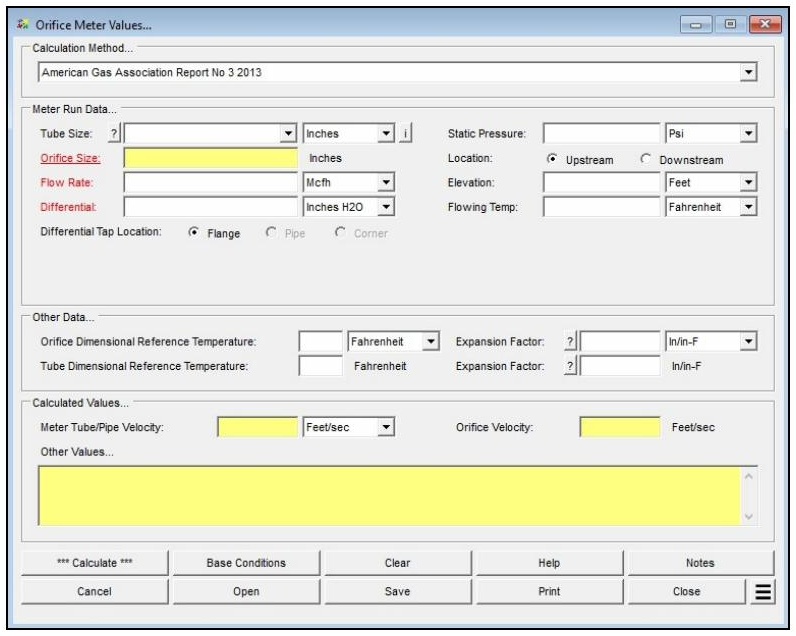
| Parameter | Description |
|---|---|
| Calculation Method | Specifies which method is used to perform the calculation (AGA Report No. 3 — 1985, 1992, or 2013; or ISO 5167). |
| Tube Size | Specifies the inside diameter of the meter tube in which the meter is installed. Click the ? command button to select a size using the Pipe Selection screen; if a Size/Type Code is selected, the corresponding Inside Diameter is read from the Pipe Property Table. |
| Orifice Size | Specifies or displays the orifice diameter value. May be designated the unknown (calculated) item. |
| Flow Rate | Specifies or displays the volumetric flow rate through the meter. May be designated the unknown (calculated) item. |
| Differential | Specifies or displays the differential pressure across the orifice plate. |
| Differential Tap Location | Specifies the location of the differential pressure tap (e.g., Flange). Only used for certain calculation methods. |
| Static Pressure | Specifies the static pressure at the orifice plate. |
| Location | Specifies the location of the static pressure tap relative to the orifice plate (Upstream or Downstream). Only used for certain calculation methods. |
| Elevation | Specifies the height above mean sea level at the meter installation. Only displayed when the Atmospheric Pressure Method in the Base Conditions is not set to “None” or “None – Entered Value”. |
| Flowing Temp | Specifies the temperature of the gas flowing through the meter. |
| Orifice Dimensional Reference Temperature | Specifies the reference temperature value for the orifice plate dimensions. |
| Tube Dimensional Reference Temperature | Specifies the reference temperature for the meter sizes. Only used for certain calculation methods. |
| Expansion Factor (Orifice & Tube) | Specifies the coefficient of linear thermal expansion factor for the orifice plate and meter tube material. Click the ? command button to select a value using a data selection screen. |
| Atm Pressure | Specifies the atmospheric pressure value at the orifice meter location. Only displayed when the Atmospheric Pressure Method in the Base Conditions is set to “None – Entered Value”. |
| Compressibility Factor (Base / Flowing / Standard) | Specifies the compressibility factor for the base, flowing, and standard conditions. Only displayed when the Compressibility Factor Method in the Base Conditions is set to “None – Entered Values”. |
| Base Pressure / Base Temperature | Set on the Base Conditions screen. Establishes the base (reference) pressure and temperature used for the calculation. |
| Atmospheric Pressure Method | Set on the Base Conditions screen. Determines how atmospheric pressure is established and controls whether the Elevation or Atm Pressure fields are displayed. |
| Compressibility Factor Method | Set on the Base Conditions screen. Determines how the compressibility factors are computed; if set to “None – Entered Values”, the factors must be entered manually. |
Part 2: Outputs/Reports
- If you need to modify an input parameter, click the CALCULATE button after the change.
- Review the Other Values panel for additional intermediate results, which vary by calculation method and can be used to verify results against published example calculations.
- To SAVE the calculation, click the Save command button (calculation files use the .orf extension).
- To print the data values and results, click the Print command button and configure the Print Settings screen.
- To calculate a table of results over a range of values, use the Calculate Table Of Results Additional Action.
- To compare results by changing a value without re-entering all data, use the Open Duplicate Calculation Additional Action.
Results
| Output | Description |
|---|---|
| Flow Rate | Displays the volumetric flow rate through the meter when designated the unknown (calculated) item. |
| Orifice Size | Displays the orifice diameter when designated the unknown (calculated) item. |
| Meter Tube/Pipe Velocity | Displays the calculated velocity of the flow through the upstream meter tube, based on the temperature-adjusted tube diameter at the specified static pressure. Expressed in the selected dimensional unit (e.g., ft/sec). |
| Orifice Velocity | Displays the calculated velocity of the flow stream through the orifice, based on the temperature-adjusted orifice diameter at the specified static pressure. |
| Other Values | Displays additional intermediate results that vary depending on the selected calculation method. These values can be used to verify and compare the calculation against other procedures or published example calculations. |
Note: The red-colored labels indicate which items may be calculated; an underlined label identifies the item selected as the unknown. Only one red item may be selected to be calculated, and all remaining items must be known. The number of decimal places shown for any calculated item can be set under File > Preferences > Decimals.
References
- American Gas Association, Report No. 3, Orifice Metering Of Natural Gas, Second Edition, 1985.
- American Gas Association, Report No. 3, Orifice Metering Of Natural Gas, Third Edition, 1992.
- International Standard Organization, ISO 5167-1, Measurement of fluid flow by means of pressure differential devices, First Edition, 1991.
- American Gas Association, Report No. 3, Orifice Metering of Natural Gas and Other Hydrocarbon Fluids – Concentric, Square-edged Orifice Meters, Part 3: Natural Gas Applications, Fourth Edition, November 2013.
FAQ
-
What information do I need before running a meter calculation?
You will need the meter size/type code (selectable from the built-in meter table), the known value for either inlet pressure or flow rate, the flowing temperature, elevation or atmospheric pressure at the meter location, and base conditions including base pressure and temperature. Gas properties — particularly specific gravity — are also required, either entered manually or loaded from a gas properties file. If compressibility corrections are needed, a compressibility factor method must also be selected in Base Conditions.
-
What is the Rated Capacity Adjustment Factor and how should I interpret it?The Rated Capacity Adjustment Factor is the ratio of the meter’s actual flowing capacity (at the specified operating conditions) to its nameplate rated capacity. A factor greater than 1.0 indicates the meter can handle more standard volume flow than its nameplate rating under the given conditions — typically because the operating pressure is higher than the rated pressure. The factor is useful for confirming that a given meter size can handle the required flow at the intended operating pressure
-
Are there any limitations or assumptions in the calculation I should be aware of?Yes. GASCalc assumes the compressibility factor at rated base conditions (Z_BR) equals 1.0 and that the rated temperature (T_R) is 60 °F. The calculator does not predict rotor speed or enforce manufacturer speed limits — exceeding the meter’s maximum rated speed can cause immediate or premature mechanical failure, so results must be checked against the manufacturer’s specifications. Additionally, there is no common consensus standard for meter sizing, so this method may differ from the approach used by a specific meter manufacturer.
-
When should I use the Meter Values calculator versus the Meter MatchMaker?Use the Meter MatchMaker when you have not yet selected a meter and need to identify which size and type best fits a given application. Once a specific meter model has been chosen, use that meter’s Values calculator to confirm or compute the flow rate or inlet pressure at defined operating conditions and to determine the Rated Capacity Adjustment Factor.