
This application calculates the various values associated with the flow through a turbine meter, including flow rate, adjusted minimum flow rate, estimated pressure differential, rangeability, and the rated capacity adjustment factor. It supports multiple calculation methods and adjusts meter capacity for actual operating pressure, temperature, gas properties, and compressibility conditions.
Note: This calculator does not predict turbine rotor speed. Always consult the specific manufacturer’s documentation regarding meter speed limits to avoid premature meter failure.
Background
There are various methods and devices used to measure the flow of gas at a specific location. These devices are generally referred to as “meters.” One type is the inferential meter, which infers the volumetric flow rate from another parameter. In the case of a turbine meter, the volumetric flow rate is computed based on the velocity of a spinning turbine rotor.
Manufacturers generally rate a turbine meter at a specific inlet pressure. It has been a long-standing industry practice to use turbine meters under conditions different from the rated conditions. In many cases, a meter is used when the actual flow through it exceeds its rated capacity. This allows smaller meters to be used for larger applications.
Effect of Operating Pressure on Capacity
There is essentially one parameter that affects the “capacity” of a turbine-type meter, the operating pressure. Because gas is compressible, as the operating pressure changes, the gas density also changes. The density change affects both the gas velocity and the number of standard volumes that pass through the meter for a given flow velocity. If the pressure is increased, the gas density increases, and therefore more standard volumes are contained within the physical volume of gas passing through the meter, resulting in more total standard volumes passing through over a specific period of time.
Rangeability and Flow Limits
Manufacturers publish both a minimum and a maximum flow rate for turbine meters. Operating within these values ensures that gas flow measurements are within specified accuracy limits. The rangeability is an indication of the ratio between the maximum and minimum flow rates. The minimum and maximum capacity ratings, as well as the rangeability, are all affected by operating conditions. The differential pressure across the meter increases with increasing operating pressure and flow rate.
The maximum amount of gas that can be safely and accurately passed through a specific turbine meter depends on the speed at which the turbine rotor is spinning. Each meter has a specific speed limit; exceeding this limit will likely result in immediate or premature failure of the meter. If the turbine speed needs to be limited, a flow-limiting orifice or nozzle can be installed upstream of the meter.
Equations
Generic Turbine Meter Flow
As implemented in GASCalc, this method uses an equation derived from several industry references. The maximum capacity at flowing conditions is given by:
Q_F = Q_R \times \left[\frac{P_F}{P_R}\right] \times \left[\frac{SG_R}{SG}\right]^{0.5} \times \left[\frac{T_R}{T_F}\right]^{0.5} \times \left[\frac{Z_R}{Z_F}\right]^{0.5}Q_F = Q_R \times \left[\frac{P_F}{P_R}\right] \times \left[\frac{SG_R}{SG}\right]^{0.5} \times \left[\frac{T_R}{T_F}\right]^{0.5} \times \left[\frac{Z_R}{Z_F}\right]^{0.5}
Where:
QF — Maximum Meter Capacity at Flowing (Metered) Conditions, ft3
QR — Maximum Meter Capacity at Rated Conditions Converted to Base Conditions, ft3
PF — Pressure at Flowing (Metered) Conditions, psia
PR — Pressure at Rated Conditions, psia
SGR — Specific Gravity at Rated Conditions
SG — Specific Gravity of Flowing (Metered) Gas
TR — Temperature at Rated Conditions, °R (assumed to be 60°F)
TF — Temperature at Flowing (Metered) Conditions, °R
ZR — Compressibility Factor at Rated Conditions
ZF — Compressibility Factor at Flowing (Metered) Conditions
PF = PFG + PATM, where PATM is Atmospheric Pressure at the Metered Location (psia) and PFG is Gauge Pressure at Flowing Conditions (psig)
PR = PRG + PR_ATM, where PR_ATM is Atmospheric Pressure at Rated Conditions (psia) and PRG is Gauge Pressure at Rated Conditions (psig)
Where QR is first derived from:
Q_R = Q_{RATED} \times \left[\frac{P_{BR}}{P_B}\right] \times \left[\frac{T_B}{T_{BR}}\right] \times \left[\frac{Z_B}{Z_{BR}}\right]Q_R = Q_{RATED} \times \left[\frac{P_{BR}}{P_B}\right] \times \left[\frac{T_B}{T_{BR}}\right] \times \left[\frac{Z_B}{Z_{BR}}\right]
Where:
QR — Meter Maximum Capacity at Rated Conditions Converted to Specified Base Pressure and Temperature, cf
QRATED — Meter Maximum Capacity at Rated Base Pressure and Temperature, ft3
PBR — Base Pressure at Rated Conditions, psia
PB — Base Pressure, psia
TB — Base Temperature, °R
TBR — Base Temperature at Rated Conditions, °R
ZB — Compressibility Factor at Specified Base Conditions
ZBR — Compressibility Factor at Rated Base Conditions [Assumed to be 1.0]
Turbine Meter Minimum Flow
The adjusted minimum flow rate at flowing conditions is calculated as:
Q_{FMIN} = Q_{RMIN} \times \left[\frac{P_F}{P_R}\right]^{0.5} \times \left[\frac{SG_R}{SG}\right]^{0.5} \times \left[\frac{T_R}{T_F}\right]^{0.5} \times \left[\frac{Z_R}{Z_F}\right]^{0.5}Q_{FMIN} = Q_{RMIN} \times \left[\frac{P_F}{P_R}\right]^{0.5} \times \left[\frac{SG_R}{SG}\right]^{0.5} \times \left[\frac{T_R}{T_F}\right]^{0.5} \times \left[\frac{Z_R}{Z_F}\right]^{0.5}
Where:
QFMIN — Minimum Meter Capacity at Flowing (Metered) Conditions, ft3
QRMIN — Minimum Meter Capacity at Rated Conditions Converted to Base Conditions, ft3
PF — Pressure at Flowing (Metered) Conditions, psia
PR — Pressure at Rated Conditions, psia
SGR — Specific Gravity at Rated Conditions
SG — Specific Gravity of Flowing (Metered) Gas
TR — Temperature at Rated Conditions, °R [Assumed to be 60°F]
TF — Temperature at Flowing (Metered) Conditions, °R
ZR — Compressibility Factor at Rated Conditions
ZF — Compressibility Factor at Flowing (Metered) Conditions
Where QRMIN is first derived from:
Q_{RMIN} = Q_{RATED\text{-}MIN} \times \left[\frac{P_{BR}}{P_B}\right] \times \left[\frac{T_B}{T_{BR}}\right] \times \left[\frac{Z_B}{Z_{BR}}\right]Q_{RMIN} = Q_{RATED\text{-}MIN} \times \left[\frac{P_{BR}}{P_B}\right] \times \left[\frac{T_B}{T_{BR}}\right] \times \left[\frac{Z_B}{Z_{BR}}\right]
Where:
QRMIN — Meter Minimum Capacity at Rated Conditions Converted to Specified Base Pressure and Temperature, ft3
QRATED-MIN — Meter Minimum Capacity at Rated Base Pressure and Temperature, ft3
PBR — Base Pressure at Rated Conditions, psia
PB — Base Pressure, psia
TB — Base Temperature, °R
TBR — Base Temperature at Rated Conditions, °R
ZB — Compressibility Factor at Specified Base Conditions
ZBR — Compressibility Factor at Rated Base Conditions [Assumed to be 1.0]
Turbine Meter Rangeability
The rangeability represents the maximum-to-minimum capacity ratio of the meter at the specified operating conditions:
RANGE = \frac{Q_F}{Q_{FMIN}}RANGE = \frac{Q_F}{Q_{FMIN}}
Where:
RANGE — Turbine Meter Rangeability
QF — Meter Maximum Capacity at Flowing (Metered) Conditions, ft3
QFMIN — Meter Minimum Capacity at Flowing (Metered) Conditions, ft3
Turbine Meter Pressure Differential
The estimated pressure differential across the meter at flowing conditions is:
DP_F = DP_R \times \left[\frac{P_F}{P_R}\right] \times \left[\frac{SG}{SG_R}\right] \times \left[\frac{T_R}{T_F}\right] \times \left[\frac{Z_R}{Z_F}\right] \times \left[\frac{Q_F}{Q_R}\right]^2 + DP_{FRICTION}DP_F = DP_R \times \left[\frac{P_F}{P_R}\right] \times \left[\frac{SG}{SG_R}\right] \times \left[\frac{T_R}{T_F}\right] \times \left[\frac{Z_R}{Z_F}\right] \times \left[\frac{Q_F}{Q_R}\right]^2 + DP_{FRICTION}
Where:
DPF — Pressure Differential at Flowing (Metered) Conditions, psia
DPR — Pressure Differential at Rated Conditions, psia
PF — Pressure at Flowing (Metered) Conditions, psia
PR — Pressure at Rated Conditions, psia
SG — Specific Gravity of Flowing (Metered) Gas
SGR — Specific Gravity at Rated Conditions
TR — Temperature at Rated Conditions, °R [Assumed to be 60°F]
TF — Temperature at Flowing (Metered) Conditions, °R
ZR — Compressibility Factor at Rated Conditions
ZF — Compressibility Factor at Flowing (Metered) Conditions
QF — Maximum Meter Capacity at Flowing (Metered) Conditions, ft3
QR — Maximum Meter Capacity at Rated Conditions Converted to Base Conditions, ft3
DPFRICTION — Frictional Pressure Loss, psia
Rated Capacity Adjustment Factor
The rated capacity adjustment factor represents the multiplication factor required to convert the meter’s rated capacity to its actual capacity at the specified base and flowing conditions:
FACTOR = \frac{Q_F}{Q_{RATED}}FACTOR = \frac{Q_F}{Q_{RATED}}
Where:
FACTOR — Rated Capacity Adjustment Factor, dimensionless
QF — Meter Maximum Capacity at Flowing (Metered) Conditions, cf
QRATED — Meter Maximum Capacity at Rated Base Pressure and Temperature, cf
Case Guide
Part 1: Create Case
- Select the Turbine Meter application from the Meters Module.
- To create a new case, click the “Add Case” button.
- Enter Case Name, Location, Date, and any necessary notes.
- Click the Base Conditions command button. Set the Base Pressure, Base Temperature, and select or enter Gas Properties. Choose the Atmospheric Pressure Method and Compressibility Factor Method as appropriate.
- Click Apply to save base condition settings and return to the calculation screen.
- From the Calculation Method list, select the desired method (e.g., Generic Turbine Meter Flow).
- Click on the red label of the item to be calculated (the “unknown” value) until the label is underlined — only one unknown may be selected at a time.
- Select the desired dimensional units for all data items.
- Enter values for all known data items (Meter Size/Type, Inlet Pressure, Elevation, Flowing Temperature, etc.).
- Click the Calculate command button to compute results.
Input Parameters
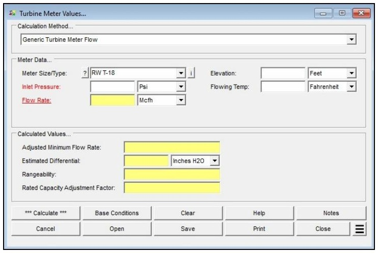
| Parameter | Description |
|---|---|
| Calculation Method | Specifies which method is used to perform the calculation (e.g., Generic Turbine Meter Flow). |
| Meter Size/Type | Specifies the meter Size/Type Code. Click the ? command button to select a meter using the Meter Selection screen. |
| Inlet Pressure | Specifies or displays the pressure at the inlet (upstream) side of the meter. May be selected as the unknown by clicking its red label until underlined. |
| Flow Rate | Specifies or displays the flow rate through the meter. May be selected as the unknown by clicking its red label until underlined. |
| Elevation | Specifies the height above mean sea level at the meter location. Only displayed when the Atmospheric Pressure Method in Base Conditions is not set to “None” or “None – Entered Value.” |
| Flowing Temp | Specifies the temperature of the gas flowing through the meter. |
| Atm Pressure | Specifies the atmospheric pressure value at the meter location. Only displayed when the Atmospheric Pressure Method in Base Conditions is set to “None – Entered Value.” |
| Compressibility Factor (Base) | Specifies the compressibility factor value for the specified base conditions. Only displayed when the Compressibility Factor Method in Base Conditions is set to “None – Entered Values.” |
| Compressibility Factor (Flowing) | Specifies the compressibility factor value for the specified flowing conditions. Only displayed when the Compressibility Factor Method in Base Conditions is set to “None – Entered Values.” |
Part 2: Outputs/Reports
- u003cliu003eIf you need to modify an input parameter, click the CALCULATE button after the change.u003c/liu003eu003cliu003eTo SAVE, fill out all required case details then click the SAVE button.u003c/liu003eu003cliu003eTo rename an existing file, click the SAVE As button. Provide all case info then click SAVE.u003c/liu003eu003cliu003eTo generate a REPORT, click the REPORT button.u003c/liu003eu003cliu003eThe user may export the Case/Report by clicking the Export to Excel icon.u003c/liu003eu003cliu003eTo delete a case, click the DELETE icon near the top of the widget.u003c/liu003e
Results
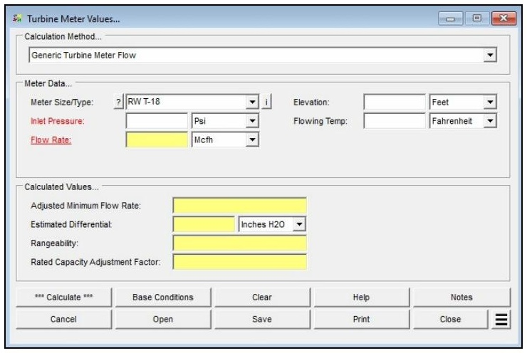
| Output | Description |
|---|---|
| Inlet Pressure | Specifies or displays the pressure at the inlet (upstream) side of the meter. May be selected as the unknown by clicking its red label until underlined. |
| Flow Rate | Specifies or displays the flow rate through the meter. May be selected as the unknown by clicking its red label until underlined. |
| Adjusted Minimum Flow Rate | Displays the minimum flow rate for the meter, adjusted for the specified operating conditions. |
| Estimated Differential | Displays the estimated pressure differential across the meter at the specified operating conditions. |
| Rangeability | Displays the maximum-to-minimum capacity rangeability for the meter, adjusted for the specified operating conditions. |
| Rated Capacity Adjustment Factor | Displays the calculated rated capacity adjustment factor — the multiplier required to convert the meter’s rated capacity to its actual capacity at the specified base and flowing conditions, accounting for pressure, temperature, differential, specific gravity, compressibility, atmospheric pressure, and base conditions. |
References
- American Gas Association — Measurement, GEOP Series Book M-1, 1993.
- American Gas Association — Measurement of Natural Gas by Turbine Meters, Report No. 7, 2006.
FAQ
-
What information do I need before running a meter calculation?
You will need the meter size/type code (selectable from the built-in meter table), the known value for either inlet pressure or flow rate, the flowing temperature, elevation or atmospheric pressure at the meter location, and base conditions including base pressure and temperature. Gas properties — particularly specific gravity — are also required, either entered manually or loaded from a gas properties file. If compressibility corrections are needed, a compressibility factor method must also be selected in Base Conditions.
-
What is the Rated Capacity Adjustment Factor and how should I interpret it?The Rated Capacity Adjustment Factor is the ratio of the meter’s actual flowing capacity (at the specified operating conditions) to its nameplate rated capacity. A factor greater than 1.0 indicates the meter can handle more standard volume flow than its nameplate rating under the given conditions — typically because the operating pressure is higher than the rated pressure. The factor is useful for confirming that a given meter size can handle the required flow at the intended operating pressure
-
Are there any limitations or assumptions in the calculation I should be aware of?Yes. GASCalc assumes the compressibility factor at rated base conditions (Z_BR) equals 1.0 and that the rated temperature (T_R) is 60 °F. The calculator does not predict rotor speed or enforce manufacturer speed limits — exceeding the meter’s maximum rated speed can cause immediate or premature mechanical failure, so results must be checked against the manufacturer’s specifications. Additionally, there is no common consensus standard for meter sizing, so this method may differ from the approach used by a specific meter manufacturer.
-
When should I use the Meter Values calculator versus the Meter MatchMaker?Use the Meter MatchMaker when you have not yet selected a meter and need to identify which size and type best fits a given application. Once a specific meter model has been chosen, use that meter’s Values calculator to confirm or compute the flow rate or inlet pressure at defined operating conditions and to determine the Rated Capacity Adjustment Factor.