
Introduction
The Ultrasonic Meter calculator determines the volumetric flow rate through an ultrasonic meter given the meter body diameter, flow velocity, inlet pressure, flowing temperature, and gas properties. Results can be expressed as either a standard (base-condition) volumetric flow rate or as an actual volumetric flow rate. Two calculation methods are provided: one for actual-condition flow and one for standard/base-condition flow.
Important: Ultrasonic meters have manufacturer-specified minimum and maximum acceptable velocity limits within which measurement accuracy is maintained. Operating outside these bounds does not damage the meter, but results will fall outside the acceptable accuracy range. Always verify that the computed velocity is within the meter’s rated velocity window for the intended application.
Background
An ultrasonic meter is an inferential meter — rather than directly displacing or capturing gas, it measures a physical parameter (gas velocity) and infers the volumetric flow rate from that measurement combined with known pipe geometry, pressure, and temperature. The velocity is determined by measuring the transit-time difference between opposing high-frequency sound waves sent across the meter body: one travelling with the flow and one against it. The difference in transit times is directly proportional to the average gas velocity along the acoustic path. Because ultrasonic meters contain no moving parts, they are highly durable and require minimal maintenance.
Effect of Diameter
The meter body’s inside diameter is one of the two dominant parameters controlling capacity. Flow rate scales with the cross-sectional area of the meter bore, which varies with the square of the diameter. Many ultrasonic meter manufacturers do not publish a precise internal bore dimension; their literature typically recommends using the inside diameter of standard-schedule or standard-wall-thickness steel pipe of the same nominal size as a suitable approximation.
Effect of Operating Pressure
Operating pressure is the other primary capacity parameter. Increasing the meter pressure increases the density of the gas at the measurement point, so a higher number of standard volumes pass through the meter for any given measured velocity. This is the principal means by which an ultrasonic meter’s effective capacity is adjusted for a given installation.
A subtle ambiguity exists in the literature regarding exactly where along the meter the pressure should be taken for volumetric calculations. AGA Report No. 9 does not specify a preferred pressure measurement location, and the pressure difference between the upstream and downstream faces of an ultrasonic meter is small (though non-zero). Using the downstream pressure will yield a slightly lower calculated flow rate than using the upstream pressure. For meter sizing purposes, using the known or assumed inlet (upstream) pressure is acceptable practice.
Actual vs. Standard Flow Rate
Ultrasonic meter capacities are sometimes reported as actual volumetric flow rates rather than standard volumetric flow rates. The standard (base-condition) flow rate is the actual flow rate corrected from the flowing pressure, temperature, and compressibility factor to the specified base conditions. When the Actual option is selected in the calculator, the flowing and base pressure and temperature values are not used in the computation, and the result is reported as the actual in-situ volume.
Equations
Generic Ultrasonic Meter Flow — Actual Conditions
When reporting flow at actual (in-situ) conditions, the volumetric flow rate is calculated directly from the measured velocity and the meter bore area:
Q = 19.635 \times V \times D^2
Generic Ultrasonic Meter Flow — Standard/Base Conditions
When reporting flow at standard (base) conditions, the actual volumetric flow rate is further corrected for pressure, temperature, and compressibility to convert it to the specified base conditions:
Q = 19.635 \times V \times D^2 \times \frac{P_F}{P_B} \times \frac{T_B}{T_F} \times \frac{Z_B}{Z_F}Where:
Q − Volumetric flow rate at the specified base pressure and temperature (cfh)
V − Flow velocity (feet/sec)
D − Inside diameter of the meter body (inches)
PF − Flowing pressure (psia); PF = PF,gauge + PATM
PB − Base pressure (psia)
TF − Average gas flowing temperature (Rankine)
TB − Base temperature (Rankine)
ZF − Compressibility factor at flowing conditions (dimensionless)
ZB − Compressibility factor at base conditions (dimensionless)
PATM − Atmospheric pressure at the meter location (psia)
Note: The constant 19.635 is derived from the unit conversion of the cross-sectional area formula for a circular bore (
Case Guide
Part 1: Create Case
- Select the Ultrasonic Meter application from the Meters Module.
- From the Meters menu, select the Ultrasonic Meter item. The Ultrasonic Meter Values calculation screen will be displayed.
- Click the Clear button to set all values to blank (null).
- Click the Base Conditions button. Enter the appropriate base pressure and temperature, select or enter gas property values, choose the Atmospheric Pressure Method, and select the Compressibility Factor Method. Click Apply to save and return.
- From the Calculation Method list, select Generic Ultrasonic Meter Flow. To report results at actual (in-situ) conditions, select the Actual checkbox next to the Flow Rate field; leave it unselected to report at standard/base conditions.
- Click the red label of the item to be calculated — Flow Rate, Inside Diameter, Meter Pressure, or Velocity — until it is underlined.
- Click the ? button next to Meter Size/Type to open the Meter Selection screen and choose the appropriate ultrasonic meter. If a matching pipe size is available for the meter body, click the ? button next to Inside Diameter to select it from the Pipe Property Table; otherwise enter the diameter directly.
- Enter all known values: Meter Pressure, Velocity, Elevation, and Flowing Temperature. Select appropriate dimensional units for each field.
- Click the Calculate button to compute the result.
Input Parameters
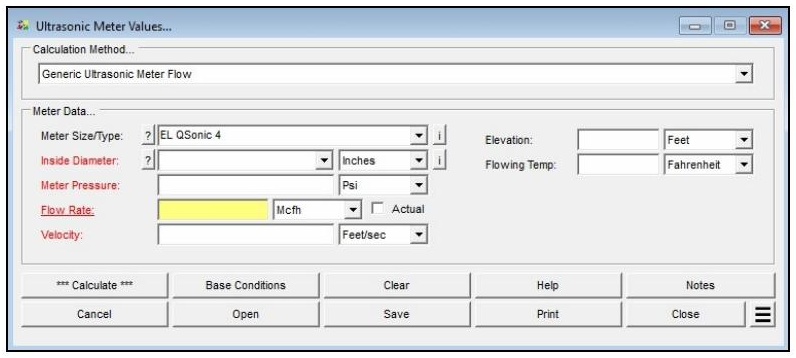
| Parameter | Description |
|---|---|
| Calculation Method | Specifies which method is used to perform the calculation. Currently only Generic Ultrasonic Meter Flow is supported. |
| Meter Size/Type | Specifies the meter Size/Type Code. Click the ? command button to select a meter using the Meter Selection screen. |
| Inside Diameter | Specifies or displays the inside diameter of the meter body. Click the ? command button to select a pipe size using the Pipe Selection screen, or enter directly. |
| Meter Pressure | Specifies or displays the pressure at the inlet (upstream) side of the meter. |
| Flow Rate | Specifies or displays the flow rate through the meter. Represents standard or actual volume depending on the Actual option. Click the red label to select this as the unknown to be solved. |
| Actual | When selected, the flow rate is reported as the actual (in-situ) volumetric flow rate and the flowing and base pressure and temperature values are ignored. |
| Velocity | Specifies or displays the gas velocity through the meter opening. |
| Elevation | Specifies the height above mean sea level at the meter location. Displayed when the Atmospheric Pressure Method in Base Conditions is not set to “None” or “None – Entered Value.” |
| Flowing Temp | Specifies the temperature of the gas flowing through the meter. |
| Atm Pressure | Specifies the atmospheric pressure at the meter location. Displayed only when the Atmospheric Pressure Method in Base Conditions is set to “None – Entered Value.” |
| Compressibility Factor (Base) | Specifies the compressibility factor for the specified base conditions. Displayed only when the Compressibility Factor Method in Base Conditions is set to “None – Entered Values.” |
| Compressibility Factor (Flowing) | Specifies the compressibility factor for the specified flowing conditions. Displayed only when the Compressibility Factor Method in Base Conditions is set to “None – Entered Values.” |
Part 2: Outputs/Reports
- If you need to modify an input parameter, update the value and click the CALCULATE button again.
- To SAVE, click the Save command button. Provide a file name and location (.usm file).
- To open a previously saved calculation, click the Open command button and select the .usm file.
- To generate a REPORT, click the Print command button to access the Print Settings screen.
- To compare results for different meter sizes or operating pressures, use Additional Actions > Open Duplicate Calculation.
- To add a title or notes to the calculation, click the Notes command button.
Results
| Output | Description |
|---|---|
| Inside Diameter | The meter body bore used in the calculation. Displayed when selected as the unknown to be solved (inches or mm). |
| Meter Pressure | The pressure at the inlet (upstream) side of the meter. Displayed when selected as the unknown to be solved (psig or millibar). |
| Flow Rate | The computed volumetric flow rate at standard base conditions, or at actual flowing conditions when the Actual option is selected. Displayed when selected as the unknown to be solved (cfh, Mcfh, or m³/h). |
| Velocity | The gas velocity through the meter opening. Displayed when selected as the unknown to be solved (ft/sec or m/sec). |
References
- Gas Processors Suppliers Association — Engineering Data Book, Eleventh Edition (FPS), 1998.
- American Gas Association — Report No. 9, Measurement of Gas by Multipath Ultrasonic Meters, Second Edition, 2007.
FAQ
-
What information do I need before running a meter calculation?
You will need the meter size/type code (selectable from the built-in meter table), the known value for either inlet pressure or flow rate, the flowing temperature, elevation or atmospheric pressure at the meter location, and base conditions including base pressure and temperature. Gas properties — particularly specific gravity — are also required, either entered manually or loaded from a gas properties file. If compressibility corrections are needed, a compressibility factor method must also be selected in Base Conditions.
-
What is the Rated Capacity Adjustment Factor and how should I interpret it?The Rated Capacity Adjustment Factor is the ratio of the meter’s actual flowing capacity (at the specified operating conditions) to its nameplate rated capacity. A factor greater than 1.0 indicates the meter can handle more standard volume flow than its nameplate rating under the given conditions — typically because the operating pressure is higher than the rated pressure. The factor is useful for confirming that a given meter size can handle the required flow at the intended operating pressure
-
Are there any limitations or assumptions in the calculation I should be aware of?Yes. GASCalc assumes the compressibility factor at rated base conditions (Z_BR) equals 1.0 and that the rated temperature (T_R) is 60 °F. The calculator does not predict rotor speed or enforce manufacturer speed limits — exceeding the meter’s maximum rated speed can cause immediate or premature mechanical failure, so results must be checked against the manufacturer’s specifications. Additionally, there is no common consensus standard for meter sizing, so this method may differ from the approach used by a specific meter manufacturer.
-
When should I use the Meter Values calculator versus the Meter MatchMaker?Use the Meter MatchMaker when you have not yet selected a meter and need to identify which size and type best fits a given application. Once a specific meter model has been chosen, use that meter’s Values calculator to confirm or compute the flow rate or inlet pressure at defined operating conditions and to determine the Rated Capacity Adjustment Factor.